
Investigation of the mechanisms for working hydraulic shears CCM
Contents
- Introduction
- 1 Theme urgency
- 2 Technology casting in CCM
- 3 Methods of cutting continuously cast billets and analysis of existing designs of scissors
- 4 Application and design of hydraulic shears CCM
- References
Introduction
Continuous casting is the most effective metallurgical process. Among the mechanisms of CCM mechanisms perform a specific function of cutting the workpiece to length provides a link between the continuous casting process and batch process bunching bars. Ensuring uptime scissors for cutting the workpiece is one of the priority tasks to be implemented in the steel plant since the ingot delay or stop may lead to a breach of the entire steel teeming unit.
The aim of this work is to study uptime hydraulic flying shears with chevron blades for cutting the workpiece on the caster.
This paper analyzes the process of cutting the steel billet to the shears, flame cutting method, studied the design of scissors, considered operating conditions typical failures will be calculated the stress state details. There will also be produced physical and mathematical modeling of wear and scissors.
The work will be recommendations to maintain the usable state of the machine.
1 Theme urgency
Modern production requires the provision of a continuous process because of the close connection of process elements.
The efficiency of each element is a determining factor in the continuous operation of the entire production cycle and directly affects the ability to perform the planned orders in accordance with the schedule.
One of the elements of the cutting-to-length rolled into hot or cold are the shears. In the course of their work wear as a hydraulic actuator, and the knives, which leads to failure, unplanned shutdowns and necessary, replace the blades.
Performing maintenance routinely allows to maintain or restore operation of the mechanism. Unscheduled stops lead to losses in production, direct and indirect costs of the enterprise.
Therefore, the aim of this master's work is to study the healthy state of hydraulic flying shears with chevron blades for cutting the workpiece on the caster.
2 Technology casting in CCM
The principle of the continuous casting is that the molten steel from a ladle is poured into a vigorously-cooled rectangular or square cross-section – a crystallizer where the partial solidification of the ingot is continuously drawn out, its further hardening occurs during the passage of the secondary cooling zone.The continuous casting allows to obtain a blank for rolling mills, and it can be combined with a continuous rolling in one unit.
The main advantages of continuous casting of steel in comparison with a casting mold as follows. There is no need in a large park teeming molds and trucks, in the application of stripping cranes and stationary machines for the extraction of ingot molds, and cooling systems for the preparation of compounds with the mold for casting, to installing pivot and pallets, as well as blooming and slabbing mill, and in some cases and billet mills. Reduce operational costs and energy costs, increased yield due to minimal material loss in scrap metal, liquidation of runners, a sharp decrease in the flow of metal scraps in rolling mills and so on. D. Significantly improves the quality of the metal due to the reduction of surface defects and to improve the structure of the ingot. Continuous casting process lends itself to full automation.
The most widely adopted radial machines differing from the machines of the vertical type with a bend at the height of the ingot and increased casting speed.Driving radial continuous casting machine shown in Figure 1.
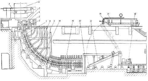
Figure 1 – Diagram of radial CCM
The structure of the machine 1 includes a teeming stand for two buckets 2, tundish 3, mounted on a self-propelled trolley 4, a copper water-cooled mold 5, 6 of the mold oscillation mechanism, Non-driven roller wiring 7, the radial section 10, the drive roller with desyatirolikovymi wiring section 8, drawing 11 is a regular machine, the machine 14 for input to the filling mold 15 and the movable gas cutting machine 16 [1].
3 Methods of cutting continuously cast billets and analysis of existing designs of scissors
For cutting continuously cast billets to length during movement of the machine used two types – mobile gas cutting and scissors. The most widely used gas cutting machines, has a relatively simple design, low metal content, and the ability to quickly replace failed nodes. However, their disadvantages are significant departure of metal in the slurry for cutting (1 – 2%) and high consumption of acetylene and oxygen. Yielding gas cutting machines for a number of indicators (weight, manufacturing cost, maintenance costs, etc.), the scissors have the advantage in the waste-free cutting of metal.
4 Application and design of hydraulic shears CCM
Shears designed for cutting on the fly defective front and back ends of continuously cast billets and cutting to length. Scissors are set for each stream caster [4].
General view of the scissors shown in Figure 2.
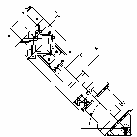
Figure 2 – General view of the mechanism of hydraulic shears
Scissors consist of welded water cooled housing, on top of which is fixed the upper crosspiece fixed blade coupled to the housing by bolts. On the stock cylinder cutting knife carrier is fixed in the lower knife moving.
Scissors are set at an angle of 45° to the horizontal plane of the cut and are supported at the bottom on the shafts and in the upper part of the supporting roller on a guide rail, located on the portal.
Guides for hydraulic shears consist of two welded racks installed on the foundation, cylindrical chrome beam resting on the two pillars and buildings, moving along the cylindrical surface of the beam, which in turn are mounted shears. To protect the cylindrical guide of scale, water and accidental impacts on the bodies established by the housing.
A hydraulic cylinder for horizontal movement on the cylindrical guide scissors (forward and backward) for cutting the workpiece in motion. It is mounted on the frame, and a rod pivotally connected to the hydraulic shears.
To synchronize the movement of hydraulic shears and moves continuously-cast billets in the housing of the hydraulic cylinder is mounted a special encoder which regulates the feed rate of the hydraulic fluid into the piston or rod cavity. For a soft stop hydraulic shears in the extreme positions in the hydraulic cylinder displacement shears have brakes, which are adjustable and made a smooth stop.
Continuously cast billet is fed from the supply roller conveyor to scissors set inclined at 45° to each stream six strand continuous casting machine, and having the ability to move in the direction of movement of the workpiece and back. Upon reaching the desired length of the front end of a moving workpiece by a command from a sensor located on the pull-leveler, a hydraulic cylinder incorporated simultaneously moving scissors and cutting cylinder that raises the lower blade support with the upper and the workpiece stationary knife. The blank is cut in the movement. At a signal from the limit switch cutting cylinder is reversed, and a knife to cut off the front end is lowered to the bottom position. Scissors, having made full speed ahead, reversed, ie, returned to its original position. At the same time cut off the front end of the blank, located on the transfer chute, moving the workpiece is facing the gear trough for the scrap box.
The measurement system dimensional length of the workpiece positioned on the workpiece the cutting line and gives the command to switch mechanisms of scissors. Cutting of moving the workpiece to length is carried out similarly trimmed front end with the difference that the severed portion of the conveying rollers of the roller table with scissors from the cutting zone at a rate greater than the moving workpiece.
Figure 3 – The construction of hydraulic shears NCMH
(Animation consists of 4 frames with a delay of 450 milliseconds
between shots;
number of cycles of reproduction 10)
In writing this essay master's work is not yet complete. Final completion: December 2015. The full text of work and materials on the topic can be obtained from the author or his manager after that date.
References
- Машины и агрегаты металлургических заводов. В 3-х томах. Т. 2. Машины и агрегаты сталеплавильных цехов. Учебник для вузов / Целиков А. И., Полухин П. И., Гребенник В. М. и др. 2-е изд., перераб. и доп. – М.:
Металлургия
. 1988., – 432 с. - Парент РФ № 2156676 Филатов А. А., Ванинский М. М., Середкин В. П., Жуков А. А. // Летучие ножницы для резки непрерывнолитого слитка // Патент России № 2156676.
- Патент РФ № 2033300 Рубинштейн Ю. Е., Бойко Ю. П., Лебедев В. И., Худанов В. К., Блинов А. П., Бояринцев А. В., Кузьменко С. Г. // Устройство для резки непрерывнолитых слитков // Патент России № 2033300.
- Установка ножниц. – Руководство по эксплуатации. – НКМЗ.
- Сатонин А. В. Исследование энергосиловых параметров процесса поперечного разделения непрерывнолитых сортовых заготовок на ножницах: Вып. 35, 2011. – (Сб. науч. тр. ДонГТУ) // Сб. науч. тр. ДонГТУ. – С. 131–137.
- Сидоров В. А. Анализ отказов узлов привода холодильника МНЛЗ / В. А. Сидоров // Металлургические процессы и оборудование. – 2009. – № 2 (16). – С. 28–33.
- Сатонин А. В. Численная методика расчета энергосиловых параметров процесса горячей поперечной резки непрерывнолитых сортовых заготовок / А. В. Сатонин, С. М. Стриченко, А. В. Завгородний, А. А. Житлова // Обработка материалов давлением: сборник научных трудов ДГМА. – Краматорск., – 2011. – № 2 (27). – С. 43–46.
- Шинкаренко О. М. Совершенствование режимов работы гидравлических прессов с насосно-аккумуляторным приводом на холостом ходе / Шинкаренко О. М., Корчак Е. С. // Обработка материалов давлением: Обработка материалов давлением: сборник научных трудов ДГМА. – Краматорск., – 2011. – № 2 (27). – С. 190–194.
- Денищенко П.Н. Анализ энергосиловых параметров процесса разделения на ножницах сортовых профилей в горячем состоянии / Денищенко П.Н., Боровик П.В., Петров П.А., Стриченко С.М. // Обработка материалов давлением: сборник научных трудов ДГМА. – Краматорск., – 2011. – № 4 (29).
- Петров П. А. Математическое моделирование энергосиловых параметров процесса поперечной резки круглых сортовых профилей / Петров П. А., Стриченко С. М., Бойко И. И., Сытник А. А. // Обработка материалов давлением: сборник научных трудов ДГМА. – Краматорск., 2012. – №1 (30). – С. 227–232.
- Боровик П. В. Теоретический анализ процесса горячей резки на ножницах / Боровик П. В. // Обработка материалов давлением: сборник научных трудов ДГМА. – Краматорск., 2012. – № 1 (30). – С. 218–222.
- Ворожко С. С. Моделирование ударной резки слитка / Ворожко С. С., Кладова О. Ю., Нарыжный А. Г., Слюсаренко Т. В. // Обработка материалов давлением: сборник научных трудов ДГМА. – Краматорск., 2012. – № 3 (32). – С. 185–191.
- Боровик П. В. Теоретический анализ бокового усилия при горячей резке параллельными ножами / Боровик П.В. // Обработка материалов давлением: сборник научных трудов ДГМА. – Краматорск., 2012. – № 4 (33). – С. 132–135.
- Боровик П. В. Повышение качества резки проката шевронными ножами / Боровик П.В. // Обработка материалов давлением: сборник научных трудов ДГМА. – Краматорск., 2013. – № 1 (34). – С. 245–250.
- Боровик П. В. Анализ напряженно-деформированного состояния металла при разделении квадратного профиля на ножницах // Обработка материалов давлением: сборник научных трудов ДГМА. – Краматорск., – 2014. – № 2 (39).
- Сатонин А. В. Имитационное моделирование спектра рабочей нагрузки процесса поперечной резки сортовых профилей на ножницах / Сатонин А. В., Боровик П. В., Петров П. А. // Обработка материалов давлением: сборник научных трудов ДГМА. – Краматорск., – 2014. – № 2 (39).
- Электронный ресурс www.findpatent.ru.