
Abstract
Content
- Introduction
- 1. Theme urgency
- 2. Goal and tasks of the research
- 3. Thermal formulation of the problem
- 4. Description energy saving modes of microalloying steel cored wire with content of calcium on the basis of a computer program
- Conclusion
- References
Introduction
In practice of modern metallurgical production one of perspective directions of increase quality metal and improvement of quality of consumer properties, not requiring considerable raw material and power expenses, there is a microalloying of steel.
Under microalloying is understood the introduction of individual elements or their compounds, residual content which not exceeding 0,1%, providing a significant impact on processes, occurring in metal and determining its phase composition, the size of the structural components, the structure and purity of the borders and border zones, and, as a consequence, improve the physical properties of the metal.
Micro-alloying additives capable of reacting with oxygen, nitrogen, sulfur and other impurities and creat the corresponding compounds, allowing to neutralize their adverse effects, that will eventually lead to the improvement of the physical properties of the metal.
1. Theme urgency
On the Fig.1 submitted the scheme of installation "ladle furnace" for the secondary treatment of steel with the possibility of its microalloying cored wire with the help of Tribe - apparatus, established on the vault of the furnace.
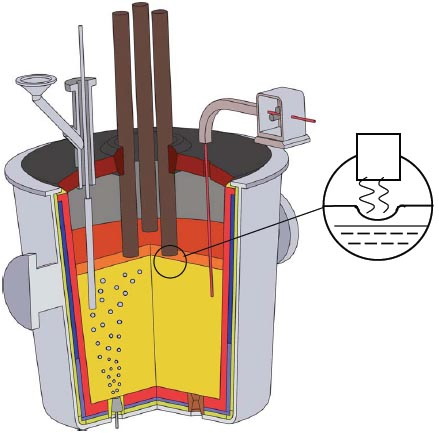
Figure 1 – General installation scheme "ladle - furnace"
The use chemically active additives in the form of pieces for vnepechnogo microalloying not very efficiently. In recent years, It became widespread method of introducing micro-alloying additives in a metal in the form of cored wire with an appropriate excipient.
Advantages of introducing alloying additives in the form of cored wire compared with traditional methods of doping:
- More high the degree of assimilation of elements;
- The possibility of receipt steel with strictly regimented content of active elements;
- Reproducibility of results;
- Possibility of serial continuous casting of various steel grades;
- Receiving of a stable mechanical properties;
- High technological and economic efficiency of the process.
2. Goal and tasks of the research
Master's work is devoted to development of Energy and resource Saving modes of microalloying liquid steel cored wired based on computer simulation processes of heat and mass transfer. This will determine the optimal speed input cored wire, at which the is reached maximum coefficient assimilation of CaSi additives, that in turn will reduce the specific consumption expensive cored wire.
3. Thermal formulation of the problem
When microalloying the molten steel most important parameter is the input speed cored wire into the melt. If it is low, it leads to her melting and dissolution of the filler cored wire in the upper layers bath, resulting we get an uneven distribution calcium on height of bucket. At excessively high speed input cored wire, it does not have time to melt and reaches the bottom of the bucket, is bent and exits into the upper layers melt and even in the atmosphere.
Feed rate of the cored wire must be selected so that her shell was melted in bottom volumes bucket.
For a comprehensive assessment of the impact of various factors on the time of melting flux cored wire should be used the dependence:
where d - diameter of the wire; q - density thermal flux on her surface.
Given the specificity of the problem, its mathematical formulation can be described by the Fourier heat equation in cylindrical coordinates for each area of the cored wire:
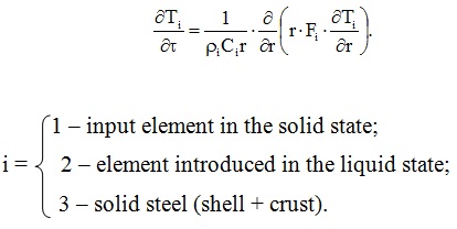
We obtain the equations in a generalized form:
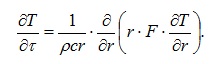
The boundary conditions for the heat equation are of the form:
1) Initial conditions:

Here: Т0 – ambient temperature; R – the radius of the region occupied by the filler powder wire at the initial time; δ – thickness of the steel shell in this moment.
2) Boundary conditions:
а) axis of symmetry (r = 0):

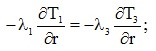
б) juncture solid filler and a steel shell Т1=Т3 (r = R):
в) juncture solid and liquid phases of the filler cored wire Т1=Тпн (r=R1):
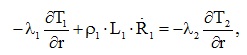
г) juncture surface of the cored wire and molten steel (r = R3):
Т3=T(R3) - freezing a crusts at Т3< Тпс
Т3=Тпс - melting shell and crust.
Здесь:
Тпн, Тпс - the liquidus temperature of the filler and the steel;
Тс0, Тс - temperature steel in volume bucket and at r=R3;
ρ1, ρ3 - density filler and steel;
L1, L3 - specific heat of phase transitions;
R1, R3 - border moving speed r=R1 and r=R3.
4. Description energy saving modes of microalloying steel cored wire with content of calcium on the basis of a computer program
Selection of the optimal speed input cored wire in molten steel creates preconditions address the issue of energy saving associated with economies of cored wire.
Numerical parametric study was conducted for CaSi wire(on the basis of СК30), the temperature of the melt in the ladle 1600°С, depth the liquid bath of 4 m.
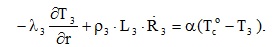
As is known, the melting stages cored wire with Silicocalcium, i.e. low melting,filler have the sequence shown on Fig.2.
At the initial time, at the stage I, geometry section cored wire it is characterized by two zones:
- The solid filler cored wire
- The steel shell cored wire with crust of molten steel (not shown in Fig.2)
Then, in stage II, during the a melting of the filler is formed a third area - melt filler cored wire. Finally, after complete melting of the filler, we are returning to the two zones, one of which, instead the solid phases filler cored wire, converted to his its liquid state.
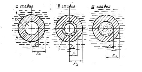
Figure 2 - Stages of a melting cored wire with Silicocalcium filler
On a measure meltdown sheath cored wire at the bottom of of the bucket (at the optimum speed enter cored wire), here is formed hearth of liquid drops silicocalcium, which emerge in the steel melt, dissolves therein.
Fig.3 depicts the received dynamics melting shell cored wire of 12 mm diameter with Silicocalcium (СК30) filler at a temperature of the liquid bath 1600°С. As can be seen from this figure, the crust began to on shell cored wire initially increases up to a certain limit, and then melt together with the shell. Feed rate cored wire in the bath determines the heat transfer intensity between the surface of the wire and the molten steel in the ladle. Because of this, aforementioned the parameter of affects the dynamics of melting cored wire.
Comparison with similar results of other studies [16, 18] shows their satisfactory agreement. At this on Fig.3 1 curve - corresponds to the work [18], 2 - The result of shown the master's work and curve 3 - processed methods of interpolation and extrapolation of the data of work [16].
How follows from the relative comparison of the curves, the use of the author more accurate empirical formula for the dimensionless heat transfer coefficient (Nusselt criterion) compared with the work of [16] gives results that bring them closer to the research [18]. In addition, the methodology used by the author relation to the traditional technology of microalloying in ladle metal cored wire more efficiently than [18]. This follows from the fact that the regarded technology eliminates as a deviation cored wire from the vertical when introduction in steel-smelting ladle (on the recommendations of the authors of studies [15, 18] ), and the absence slag layer on the surface of the cored wire in the deep layers of the liquid bath.
1 – according data V.Yu.Bolotova; 2 – results of this work; 3 – according data O.E.Polozyuka;
Filler cored wire - CK30; Feed rate cored wire - 5 m/s; The temperature bath - 1600°С; Bath depth - 4m.
Figure 3 – Diagram of melting cored wire with a crust of steel
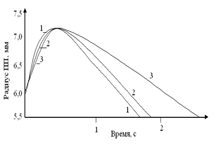
Information about the impact of densities the heat flow directed to the surface of the cored wire, for a while the melting of its shell with the frozen crust represented Fig.4. When determining the q used found heat transfer coefficient α, and as the surface temperature of the flux cored wire was taken liquidus temperature of the steel. The graphs it allows a quantitatively find the relevant time, while monotonically decreasing dependence are obvious. Fig.4 shows that most rapidly melts wire of smaller diameter.
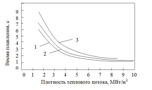
1 – diameter 8mm; 2 – diameter 10mm; 3 – diameter 13mm;
Figure 4 – Time melted shell cored wire and steel crust, the frozen on cored wire with silicocalcium, depending on the density of the heat flow directed onto the surface of the cored wire
To calculate the degree of assimilation of the filler [17] depending on the technology parameters input wire enough (using calculated the results of its melting) assess the local diffusion mass transfer drops filler cored wire with the molten steel (taking into account the processes of hydrodynamics and transport near the interface interfacial), based on the representation of the perfect mixing of the metal in a liquid bath.This follows from the high coefficient of convective diffusion, which lead to rapid equalization of the concentration of filler components cored wire in this area.
Time melting the fillers cored wire type Al and CaSi less than similar time for the frozen crust and steel shell.Therefore, at the time of the release of the filler from the shell it is completely liquid.
The behavior of liquid droplets of filler a manner similar to argon bubbles under purge bath because and the density of the liquid aluminum or silicocalcium in 3-3.5 times lighter than steel density at 1600°С;, and dynamic viscosity is 4-5 times lower.
Silicon, on the one hand, is readily soluble in liquid iron, and on the other hand, its diffusion coefficient is much less than that of calcium. Calcium, on the contrary, is poorly soluble in this the medium, however, its diffusion coefficient is higher.
Conclusion
Thus, in this work discussed topical issues of energy saving when microalloying steel in ladle cored wire. The work will allow to choose the optimal input speed cored that wire which in turn will reduce its flow and lead to savings.
In writing this essay master's work is not yet complete. Final completion: January 2016. Full text of theand materials on the topic can be obtained from the author or his manager after that date.
References
- Троцан А.И. Теория и практика микролегирования с учетом межкристалитной внутренней адсорбции /А.И. Троцан, И.Л. Бродецкий, А.И. Ищенко. - К.: "КИМ" - 2009. - 272 с.
- Физическое металловедение / под ред. Р.У. Кана и П. Хаазена. - М.: Металлургия, 1987. - Т.1. - С. 111-137; Т.З. - С.5-112.
- Дамаск А. Точечные дефекты в металлах/ А. Дамаск, Дж. Дине. - М.: Мир, 1966. - 291с.
- Новиков И.И. Кристаллография и дефекты кристаллической решетки / И.И. Новиков, К.М. Розин. - М.: Металлургия, 1980. - 336с.
- Штремель М.А. Прочность сплавов. Дефекты решетки / М.А. Штремель. - М.: Металлургия, 1982. - 278с.
- Глейтер Г. Большеугловые границы зерен / Г. Глейтер, Б. Чалмерс. - М.: Мир, 1975. - 376с.
- Грабский М.В. Структура границ зерен в металлах / М.В. Грабский. - М.: Металлургия, 1972. - 160с.
- Атомная структура межзеренных границ сборник статей /[пер. с англ. В.Н. Перевезенцева, В.В. Рыбина ; ред. пер. и вступит, статья А.Н. Орлова]. - М.: Мир, 1978. - 290с.
- Орлов А.М. Границы зерен в металлах / А.М. Орлов, В.М. Перевезенцев, В.В. Рыбин. - М.: Металлургия, 1980 - 154с.
- Структура межкристаллитных и межфазных границ / В.М. Косевич, В.М. Невлев, JI.C. Палатник, А.И. Федоренко. - М.: Метал¬лургия, 1980. - 256с.
- Кайбышев О.А. Границы зерен и свойства металлов / О.А. Кайбышев, Р.З. Валиев. - М.: Металлургия, 1987. - 213с.
- Bollmann W. Crystal Defects and Crystal Interfaces / W. Bollmann. - Springer Verl.; Berlin, 1970. - 244 p.
- Goodhew P. Crain Boundary Structure and Kinetics / P. Goodhew. - 1SH, 355 Metals Park, OH, 1980 - 155 p.
- Ishida Y. Fild ion microscopy observations of ordered grain boundary structures in tungaten / Y. Ishida, D.A .Smith // Scripta Met. - 1974. - V.8, № 3. - P.293-298.
- Дюдкин Д.А., Кисиленко В.В., Павлюченков И.Л., Болотов В.Ю. Ковш-печь…
- Захаров Н. И., Полозюк О. Е. Исследование процессов теплообмена при обработке жидкой стали порошковой проволокой// Приднепр. науч. вестник. – Дн. – 1997. - №17. – С. 22-26.
- Полозюк О. Е., Захаров Н. И. Кинетика массопереноса элементов при внепечной обработке стали силикокальцием или алюминием// IV регион. научно-техн. конф. Апрель, 1997: Тез. докл. – Мариуполь. – 1997. – Т. 1 – С. 5.
- Исследование процессов плавления и траектории движения проволоки при вводе в сталь /Тимошпольский В.И., Болотов В.Ю., Павлюченков И.А. и др.// Литьё и металлургия. – 1999. – №2. – С. 21-23.