
Abstract
Content
- Introduction
- 1. Purpose and objectives of the study, expected results
- 2. Expected scientific results
- 3. Practical value
- 4. Analytical review
- 4.1 Inflatable hydraulic packer
- 4.2 Packer PGE-1 set KST-1
- 4.3 Packer PDM construction VNIIBT
- 5. Description designed mechanism
- Findings
- List of sources
Introduction
In the process of drilling, casing cementing, testing and development of productive horizons, as well as their operation is necessary to temporary or permanent separation wells into separate sections.
The most advanced is the technology of zonal isolation and insulation casing packer using the devices. For example, bringing the mixture to plugging of the absorption zone through the drill pipe, which is installed at the end of the packer, a 40–60% reduction in time and cost 1.5–2.0 times reduces material consumption compared with previously used technology, which is implemented without the use of packer devices.
The use of packers in mining has long been known, but in recent years in the exploration and production drilling of wells achieved notable successes in the field of constructive solutions and technologies of application packers, and theoretical research in the field of health.
Currently, the exploration drilling using three types of packers: mechanical, hydraulic, hydro. In this work, my project is an improvement of hydro packer, whose main purpose is to improve its performance [2].
1. Purpose and objectives of the study, expected results
The purpose of the study: designed hardware technology for plugging exploration drilling conditions.
Research objectives:
- The current state of the art technology and plugging of wells.
- To investigate the effect of the design parameters of hydro packer with piston chamber on the process and technology of plugging.
- Develop a set of design documentation and technology application hydromechanical packer with piston chamber.
Object of research: technological plugging of exploration wells.
Subject of research: design parameters of hydro packer with piston chamber.
2. Expected scientific results
Develop a methodology for calculating the piston chamber packer provides a reliable seal the annulus of the well.
3. Practical value
- It is expected to improve the efficiency of grouting works through the use of volume of autonomous working fluid.
- The method of calculation of operating parameters of hydromechanical packer with piston chamber.
- The design of hydromechanical packer and technology of its application for the plugging process.
4. Analytical review
This topic will be considered hydraulic packers their characteristic feature is that the fluid pressure is used to ghosts packer in working position in which the sealing member is pressed against the borehole wall or casing. The main advantage of the hydraulic packer with respect to mechanical packers is the ability to operate at high differential fluid pressures and the possibility of the isolation annulus column at a large value of the gap. This is due to their operation. Moreover, the larger the pressure drop of fluid, the stronger the sealing element is pressed against the casing.
4.1 Inflatable hydraulic packer
The invention relates to the field of oil and gas industry and can be used to isolate the wellbore. It provides enhanced functionality by providing multiple translation packer from transport to working position and back during the descent into the well without removal. The packer is shown in Fig. 4.1., Comprising a housing mounted on it the sealing element type elastically expandable sleeve coaxially disposed in the housing the hollow stem and the main piston. They form an injection hydraulic chamber. Between the body and the trunk above the main piston mounted outer piston. It forms the main piston further cavity. This cavity through the radial holes in the barrel communicates with the tube side. The barrel is axially movable relative to the housing and the sealing member. The barrel has a shoulder for abutment in the main piston. The barrel concentrically mounted spring rests on the body. The discharge chamber is filled with clean hydraulic fluid when the packer assembly. Additional cavity filled with a borehole [5].
Pakerovanie should be done through the creation of an excess of hydraulic pressure within the tube descent and raspakerovanie - by raising pipes. The goal is achieved in the known hydraulic packer comprising a body mounted on it the sealing element type uprugorasshiryayuschagosya sleeve coaxially disposed therein a hollow barrel, primary plunger jointly defining discharge hydraulic chamber, between the enclosure and above the main piston stem an additional piston, forming with the primary piston further cavity, through which the radial bores in the barrel is communicated with the tube side, the barrel is axially movable relative to the element, and on the barrel has a shoulder for abutment in the main piston and spring are mounted concentrically and abutting the barrel in the housing, wherein the injection chamber is filled with clean hydraulic fluid when the packer assembly and the storage chamber is filled with a mixture of working well at lowering the packer.
At the free end of the housing nut-limiter installed, and on the outer piston has a shoulder, which he rests on the nut-limiter in pakerovaniya (a transfer from transport to working position).
Draft 4.1 – Inflatable hydraulic packer
Inflatable packer comprises a hydraulic body 1, formed from the outer sleeve 2 and the sleeve 3, the sealing member 4 in the form of a sleeve mounted on the sleeve 3. The sleeve has a radial holes 5 for supplying hydraulic fluid into the inner cavity 6 of the sealing member and the sealing rubber ring 7.
Inside the body 1 is a hollow shaft coaxially 8. Outside the barrel, but within the housing, concentrically arranged two pistons – 9 and an outer core 10. The chamber 11 formed by the main piston, the housing and the barrel is injection. The cavity 12 enclosed between two pistons 9 and 10, is optional, which communicates with the tube side through the radial holes 13 in the trunk. The discharge chamber 11 is filled with a clean hydraulic fluid when the packer assembly and additional cavity 12 is filled with a mixture of working well during the descent of the packer. The barrel 8 has two shoulder: the shoulder 14 rests on the bottom casing collar 15 is designed to stop the main trunk piston 9. Both cones mounted barrel lock members 16 and 17, for example as nuts. The stop member 16 for limiting the movement of the outer piston 10 upward, the lower element 17 – for urging spring 18 at a certain force. The spring 18 by centering washers 19 and 20 concentrically located on the trunk and abuts the sleeve 3.
As shown, in the static state of the packer body 1 together with the sealing member 4 fixed to the barrel 8 between its shoulder 14 and the spring 18. When the spring force to overcome possible unilateral movement relative to the body trunk.
In a particular example, the spring force of execution varies from 80 to 150 kgf.
Under the influence of the internal pressure of the housing 1 with a sealing element 4 tends to compress the spring 18 and fall down the shaft 8. However, it is under the pressure of the outer piston 10 to its collar 22 rests on the nut-stop 21 and prevents this movement.
After a short holding for 5...10 overpressure in the barrel is removed, but remains in the operating packer (swollen) state under hydrostatic pressure. This is due to differential areas on which hydraulic pressure acts inside and outside of the sealing member 4. The area of the sealing member 6 from the cavity is many times greater cone areas of the sealing element from the shell side and the annulus.
During operation of the well with increasing excess pressure in the barrel or in the annulus it acts on the main piston 9 directly or through the outer piston 10 and, through them and through the working fluid in the chamber 11 and the cavity 6 an overpressure is transmitted to the sealing member 4 from the inside. Consequently, the sealing member more tightly to the casing, increases the sealing but also proportionally increases the shear resistance force of the packer under overpressure.
To translate the packer from working to transport state overpressure inside the pipe and the annulus is removed to create a lifting force on the column inner tube 8 barrel, compressing the spring 18, moves upward. Moreover, its collar 15 by a gap before the main piston 9 begins to raise the piston. Thereby increasing the total volume of the chamber 11 and the cavity 6, and the pressure therein decreases. The hydrostatic pressure in the annulus of the seal member 4 is reduced in volume to baseline (vehicle) sizes. When lifting the barrel at the initial moment packer releasing the sealing element is pressed against the casing and together with the housing 1 is stationary until the volume reduction and loss of contact of the sealing member to the casing.
In a specific example of execution of the packer raspakerovaniya force equal to the mass of pipes lowered into the well, on which hangs a packer, plus the force of the spring 18 – (90...150) kgf, and the lift amount pipes wherein – (50...80) mm.
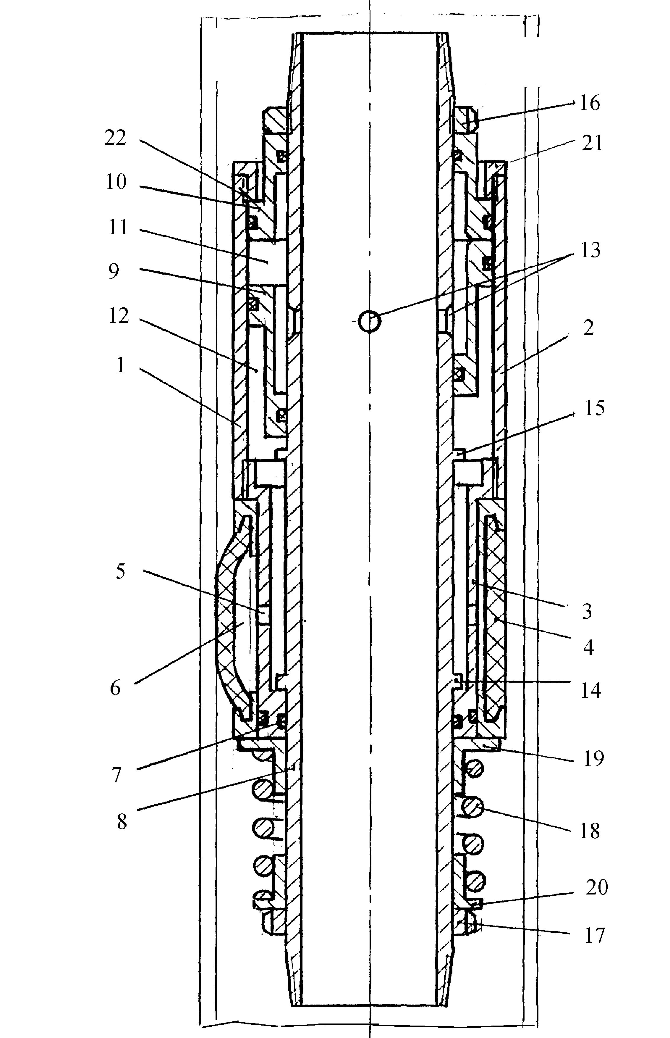
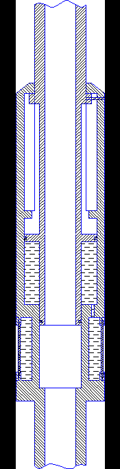
4.2 Packer PGE-1 set KST-1.
Packer PGE-1 set KST-1, shown in draw. 4.2. The barrel 12 are spring loaded (spring 8) with a shut-off valve seat 6, 7 and the flexible sleeve 11 with top and bottom 10 embedded in a fitting and coupling. Outer sealing sleeve 10 is rigidly connected by a housing 9 with the adapter 5, which in turn is screwed onto the barrel 12. The opening of the adapter plug 4 inserted in contact with the upper part of the annular projection rod 2 which Cpd left threaded adapter 5. The support 3 with holes limits the stroke in the unscrewing of the adapter. To connect to the drill string has a head 1.
Draft 4.2 – Packer PGE-1 set KST-1
To regulate the pressure drop in the bottom of the barrel has a sleeve 14 fixed pin 15 and a tip 16 with holes for the passage of fluid.
Before descending into the well cavity formed by an elastic sleeve and the barrel is filled with water at a technical disconnected casing packer 9. Then drill pipe is lowered into the well defined range, throw the ball 6 include pump. The pressure in the drill string is raised to a value less than that required to break the pin 15 and held for 3–5 minutes. When this shut-off valve 7 is opened, the pressure inside the sleeve 11 is increased, which leads to deformation and overlapping wells.
With further increase of the pressure pin 15 is destroyed, the sleeve 14 with the ball 13 is moved downward, opening holes A, which causes a sharp collapse. Shut-off valve 7 under the action of the spring 8 and the pressure drop is closed, fixing the elastic sleeve in a deformable state. Plugging the mixture through a side opening B is injected into the well. To release the packer drill pipe is rotated to the right of 8–10 rpm. As a result, the rod 2 is unscrewed from the left-hand thread 5 of the adapter and opens the tube 4. The pressure in the cavity falls, the sleeve receives the transport position and the packer is removed to the surface [1].
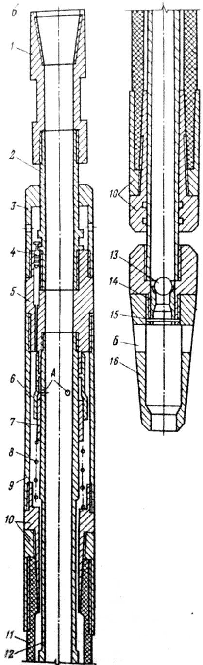
4.3 Packer PDM construction VNIIBT
Packer PDM construction VNIIBT (draw. 4.3) consists of two main components: a valve assembly, and seal the bag.
The valve assembly includes a body 5 with a cementing ports A and B inlet channels; Outer sleeve 4 is retained on the lock housing 3, which by means of two set screws ring 1; lower sleeve 9 with an inlet fixed to the housing shear elements 7; an inner sleeve 8 with inlets B, attached to the lower shear pin sleeve 6; duralumin nut 10 mounted on the bottom of the sleeve 9.
Sleeve seal includes a housing 12 with an annular cavity T and rubber-and-canvas sleeve-type sealing element 11 rigidly mounted on the housing by crimping cup.
The packer is attached to the bottom of the casing sub 13 via dispensers into the borehole casing.
Draft 4.3 – Packer PDM construction VNIIBT
When the two-stage cementing packer located between the stages of cementing, while lip - over reservoir. Cementing the first stage (lower packer) is carried out through the casing shoe, cementing the second stage (above the packer) – through hole cementing packer with top cement plug. Annulus packer prior to cementing the second stage by inflating the sealing member 11, a packer fluid from the casing. When collar cementing wells used upper cementing plug and packer carry mud or initial portion of the cement slurry.
Packer works as follows. At a given moment after cementing casing dropping ball 14, which sits on the saddle 8 and the inner sleeve overlaps the central bore of the packer. At excess pressure of 1.5–2.0 MPa over-written balloon 14 breaks the shear pins 6 and the inner sleeve 8 is moved down to the stop into the nut 10, the inlets B aligned with the inlet ports B informs the cavity G of the seal with the sleeve the inner cavity of the casing. Under the effect created in the casing of excessive fluid pressure at end sealing member which swells and closes the annular space. With further increase in pressure to a predetermined pressure 6–8 MPa shear elements 7 are destroyed, and the lower sleeve 9 together with the inner sleeve 8 and the ball 14 are moved down until it stops in the body 12 of the sleeve seal of the packer. Thus sealingly overlapped in the inlet channels are opened and cementing A hole through which the well is cemented above the packer. Cementing A hole overlap sleeve 4 at the end of the cementing process. To do this, use a cement plug, descends into the casing after the cement mortar. After landing traffic on the ring 1 on it is pressurized, and the upper sleeve 5 is moved all the way down to the bottom of the sleeve 9, covers cementing the hole A and in this position is rigidly fixed retainer 3. When the time OZTS drilled cement plug ring 1 ball 14, cement glass between them, an inner sleeve 8 and the nut 10. Metal parts plug, ball and other drillable packer parts are made of aluminum alloy [1].
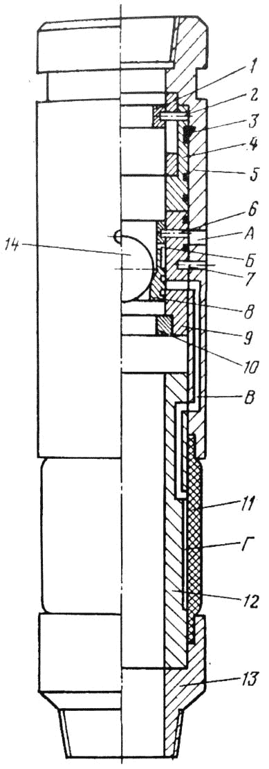
5. Description designed mechanism
The device is designed hydromechanical packer is shown in draw. 5.1
Draft 5.1 – Packer hydromechanical action
The main units of the apparatus shown in Figure 3.1, is the plunger 1 and the housing 2 to which by means of connecting rings 3 and 4 are fastened elastic chamber 5. Before descending annulus 6 and an elastic hollow chamber filled with a liquid (water, oil). Moving the rod relative to the housing is eliminated by setting the pin shank 7. In setting the packer downhole pin 7 is cut by the force imparted smooth pressing the drill string and the plunger 1 is able to move downward, squeezing the liquid through the opening 8 of the cavity 6 in the elastic chamber.
Thus there is a deformation of the elastic element, sealing the bottom zone. Removing the packer made the drill string tension.
Draft 5.2 – Principle of operation of the apparatus
Figure animated. volume – 50 kb.; the number of frames – 7; delay time – 0,5с.; the number of repetitions – 7.
Findings
A new scheme of hydromechanical packer plugging action for technological exploration wells. The results of this project indicate the technical feasibility of using this mechanism. Application of the device makes it possible to significantly reduce the time for the process of plugging due to the possibility of a quick mount mechanism and the descent into the well, as well as high quality wicking zones complications.
List of sources
- И. А. Юшков Тампонажные смеси (Раздел дисциплины
Очисные агенты и тампонажные смеси
): Учебное пособие. – Донецк: ДонНТУ, 2008. – 73 с. - В. А. Аванесов Пакеры для проведения технологических операций и эксплуатации скважин: учебное пособие / В. А. Аванесов, Е. М. Москалева. – Ухта: УГТУ, 2008. – 91 с.
- В. И. Анурьев Справочник конструктора-машиностроителя: в 3-х т. Т.1. – 5-е изд., пераб. и доп. – М.: Машиностроение, 1978. – 728 с.
- Курсове та дипломне проектування бурових робіт: Навчальний посібник / О. І. Калініченко, О. С. Юшков, Л. М. Івачев та інші – Донецьк: ДонГТУ, 1998. – 153 с.
- Справочник по бурению скважин на уголь / Г. П. Новиков, О. К. Белкин, Л. К. Клюев и др. – М.: Недра, 1988.–256 с.
- Разработка теоретических основ и технических предложений по усовершенствованию основных процессов сооружения скважин в Донбассе: отчет по НИР / кафедра ТТГР ДонНТУ. Руководитель О. И. Калиниченко – тема Н25–95-Донецк, 2000.