
Abstract
Содержание
- 1. Introduction. Theme urgency.
- 2. The image of the structures lining used for the maintenance of development workings.
- 3. Analysis of experience with the different designs shoring to maintain excavations in mines.
- 4. Conclusion.
- 5. References.
1. Introduction. Theme urgency
Coal industry – one of the leading sectors of the national economy, the most important task, which in the conditions of market economy is to increase production efficiency and reduce production costs. By 2010 it is planned to increase coal production to 100 million tons in recent years the government of Ukraine developed and approved two programs whose objective – to improve the efficiency of the coal industry. Its Program of reformanda finance ozdorovlennya print wuggle promislovist 2000–year
and Ukrainian vogella
. The implementation of these programmes for implementation in the coal industry of advanced technology to ensure the stable development of the economy of the whole country. Currently the technical condition of coal mine Foundation coal industry of Ukraine continues to deteriorate. So, about 80% of coal mines operate without renovation for over 20 years, and the third part of them was commissioned in the prewar period. Given the fact that every year for the last 14 years was lost 7.6 million tons of production capacity, to accomplish the problems the industry faced a need to dramatically increase the volume of the holding mining, among which 70–80% are firing and training. Over the past 20 years, the number of mines, leading the development of coal at a depth of 700 m, increased in 2 times.
Increasing the depth of coal seams, development on them cleaning work leads to intensive influence of rock pressure on the stability of underground excavations using various forms of its manifestation, which depend on the aggregate effect of a number of mining-geological and mining factors that are specific to the circumstances of each mine. Despite the decrease in the length of mine workings in coal mines of the Ukrainian Donbass in connection with their closing in recent years and the increase in repair costs of these workings, the status of the last is not improving. On average, 15% of them in length at the end of each year does not meet performance requirements. One of the main reasons for this is the high complexity of the maintenance works at very low (1,5–2%) their level of mechanization.
To date, nearly 90% supported the mines workings fixed metal arched pliable lining. More than half of the length of these workings deformed. As the fastening system arch support has several disadvantages. In fact, it does not support production until such time as the enclosing rocks are not destroyed and will not begin to shift to the production, loading support frame. That is, the support works in passive mode and does not prevent the destruction of the host array. Besides the main disadvantages of arch support are:
- Large metal.
- The support is not included in the work immediately after exposure of the contour generation pedigree.
- The impossibility of full mechanization of the process of attachment (tightening RAM and backing the clamping space is performed manually. The complexity of the process of fixing formulation arched support reaches 80% of the total workload of conducting production).
- The traditional design of arch support does not meet the conditions of the load (no alignment between the direction of the compliance support and direction of greatest displacement contour generation).
2. The image of the structures lining used for the maintenance of development workings
Support rock – mining structures, erected in underground mine workings to ensure their sustainability, process safety and management of mountain pressure. When this lining mountain performing one or a combination of the following functions:
- Protection of underground structures from landslides and collapses of rock
- Ensuring the design dimensions of the cross section of underground facilities for the entire period of their operation
- The perception of internal and external (in particular, water pressure in hydraulic tunnels) loads and their redistribution to involve the surrounding rock array
- Prevent the destruction, weakening of rock by weathering, disintegration, and other effects of air and water
- Reducing surface roughness and consequently the reduction of loss of air pressure and water on friction
There are the following design mining supports:
- Wooden lining. The main type – a mounting frame consisting of a roof bar is adjustable, racks (not full frame) and lezhen – full frame. Most frames come in a trapezoidal shape, a rectangular (or less) and rarely – irregular shape. Attach frames by stitches or desynchronization. Raskrepljajut wedges, puffed, her – zabudovat. The diameter of the woods – 16–32 see the Ends of the uprights point. Connection elements support: in the leg, a tooth, a thorn in the butt, in the groove, etc. the Tilt stands at RAM – 80–85. Also used in strong side rocks and roof support and log (on the swing).
- Metal lining. Used in the form trapezoidal frames, barrel, arches, rings, which can be tough, supple and articulated. Frame, rings and arches set in the range of 0.5–1.2& m and tighten wooden, reinforced concrete pipe, metal bars or mesh. Trapezoidal frame made of ibeams No. 16–27. The roof bar is adjustable with a rack connected by a special shoes or linings. The lower end of the rack rests on the tile or wooden lezhen using cast or welded Shoe. The consumption of metal for the lining is very large, there is virtually no compliance, the only advantage – ease of fabrication.
- Arched rigid support made in the form of a rigid two-hinged arches of the two polaron, United in the lock with plates and bolts.
- Arched hinge is of three and paternina. The greatest ductility provides paternina.
- Arched pliable lining. One profile is used for fixing excavations under unsteady vertical rock pressure. The arch elements connect the lap joint and tighten the two clamps. The length of overlap – 300 mm. Profiles 27, 22 and 17 kg/m; compliance is achieved by the sliding of the elements – 30–35 mm. Dignity – long service life. Requires very careful as the elements lining, otherwise, there may be twisting, distortions arches and as a consequence a loss of pliability.
- Stone and concrete lining. It is intended for fastening workings with a very long service life with a significant mountain pressure outside the influence of the treatment works. The basic form for vertical mountain pressure – vaulted with vertical walls. The arches are semicircular (hc=0,5); elevated (hc>0,5); reduced (hc<0.5). Outlines – cylindrical, defined by one radius; three-center (torispherical), defined by two radii of the three centres and parabolic. With significant mountain pressure not only from above but also from the sides or even from the soil used horseshoe shape cross section – outlines of the three centers; closed (horseshoe with a reverse arch) and the ring. The stone foundations and concrete lining bury into the sole of 25–50 cm, while the drain grooves – 50–100 cm In hard rock walls deepened by 20–30 cm without Foundation. The stone lining of the piece is placed stones on a cement-sandy solution of structure 1:3. Sacranie space saucepot breed and pour a solution of 1:5–1:7. The thickness of the filling should not exceed 10–15 cm With a significant mountain pressure used stone pliable lining: the stones are laid without mortar with the laying of the elastic strips, for example made of wood. The backing is made without the fill solution. Concrete lining durable, solid construction easy to mechanize. The sprayed-concrete lining, the resulting betalounge concreting, the most durable, adheres well to the breed. Small concrete consumption, possible full mechanization and works at the coalface. The sprayed-concrete lining is used sometimes in combination with a boom braces, sometimes – with a metal frame.
- The reinforced concrete lining. Monolithic concrete lining is used in the most critical capital workings at high loads, especially uneven. Agile-rod, hard–ibeam, channels, rail and mixed fittings. Very high complexity. Precast concrete lining is applied in the workings of the various forms and are tough and pliable. The elements it is produced by industrial methods and harvested at the place of work. The lining cost is quite high. There are two main types of supports: frame mounted vrazbezhku with bongs and panel from solid tubing, plates or blocks. The application of this lining is hampered by lack of good repuclican.
- Rod support. It is called anchor: is a system fixed in the holes of the rods located on the contour or the roof of a drift and, as if connecting the rock mass and supporting it with pickups, reference tiles or grid. Rods are used, metal, concrete, wood, stale-polimernyh. Designs castles very much. The use of sucker-lining reduces the complexity of fixing 1.5–2 times and save costs.
- Lining mates. On the curvature and width mates production increases, support frame and put in radical directions. With a cast and annular concrete lining are used either conical annular insert or conical, ring segments of variable width. Conjugation may be direct or oblique. When the flat slab in the junction to produce another chamber put a frame on which is based vernaci lining adjacent excavation. In direct near the junction with the chamber frame put the first frame of the adjacent excavation.
- Temporary piles. Support temporary piles is applied to the construction of a permanent in separate racks, incomplete frames, arches of light bars, rods, etc. the Arch can be maintained (with sustainable sides) arches from the profile, strengthen mortgages pins or rods. Here is one of the types of cladding from those supports. This pendant vernaci with puff. Temporary piles is usually removed during the construction of a permanent.
3. Analysis of experience with the different designs shoring to maintain excavations in mines
Dramatically improve technical and economic performance of mines, as well as the condition of mine workings is possible through the application of roof bolting. In coal mines abroad is the steady increase of the use of anchoring, which today is Australia – 87%, China – 83 %, USA – 52 %. This allows a 5–10 times to reduce the consumption of metal, concrete, woods; 3–5 times to increase productivity when fixing mine workings; 2–3 times to increase the rate of penetration; to halve the cost of fixing and maintaining a roof in working condition during operation.
For example, the use of anchoring in the mines of great Britain has allowed to reduce the share of expenses on carrying out of excavations in the cost of 1 ton of coal with 42% at metallwaren bracket up to 15% with a wall anchor. While the pace of excavations was 650–680 m/month.
In scientific-technical literature presents a large number of research results the nature of the interaction of various designs of supports (including anchor) with an array. This is the work of A. P. Shirokova, V. T. Glushko, A. A. Borisova, N. I. Melnikova, L. M. Erofeev, A. N. Zorin, B. K. Cocona , A. V. Remezov, I. A. Yurchenko, A. N. Shashenko, V. ;V. Vinogradov, A. Ugone, A. Costa. They have deeply investigated the formation mechanism of the load frame lining, features and regularities of deformation capacity of production of the array. However, in studies devoted to the anchor mount, mainly discussed the design of anchors, the technology of their construction and calculation of parameters. While anchors are considered as load-bearing structures, without considering the peculiarities of their interaction with the host array.
As an example, get acquainted with the results of observations in the sixth Northern conveyor drift layer m5 horizon 450 m Production length 1840 m held by the harvester. with an average speed of 280 m/month. During the mining of longwalls on stratum m5 the mine used and pillar mining system with the notch poles along strike.
The immediate roof of the seam is represented by siltstone, B3 are unstable by sowaistline close to mudstone. Above lies the Sandstone is medium-bodied. Higher – argillite medium bodied, low stability (B3). Coal seam m5 complex structure, with a total capacity of from 1.10 to 1.40 m and a compressive strength of 15 MPa. The angle of incidence – 10 degrees. Directly in the soil layer underlain by argillite medium-bodied, moderately resistant. The main ground – Sandstone is medium-bodied.
Output is fixed connected with anchor bolts from the side of the roof. Density stalepolimernyh anchors in the roof – 1.0 APK/m2.The production cross section – rectangular. Anchors with a length of 2.4 m was installed in the mine workings under the wings of the SVP-22 length 4.0 m. Output is passed to the lower bomb it, the maximum depth which Roy was 1.5 m. during the entire period of record gage station was outside the zone of influence of the stope.
In the roof and sides of excavation within the pickets 62, 72, and 89 were laid 6 integrated measuring stations equipped depth and contour reference points (Fig. 1). Measuring stations were equipped directly in the face of development.
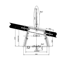
Each station consisted of 3 wells with depth up to 7 m drilled in the roof and sides of the excavation are equipped with deep frames, and one contour reference point in the soil excavation. The distance between the centers of deep benchmarks in the well ranged from 0.3 to 0.5 m. the Measurements were carried out with the help of roulette designs VNIMI (uncertainty roulette ±0.5 mm). Production measurements at the stations was carried out in accordance with the methodology VNIMI
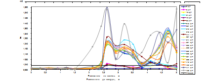
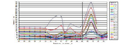
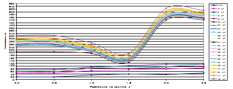
To study the development of deformation in production capacity of the array was built diagrams of displacements deep benchmarks in the wells drilled in the roof and sides, in the direction from the contour generation into the array, as well as the graphs of the variation of the coefficient of loosening between the reference points (pic. 2–9). Because the nature of the displacement of reference points on metering stations is not significantly different, and the limited volume of the article, we present the most characteristic graphs.
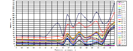
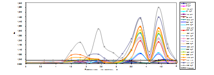
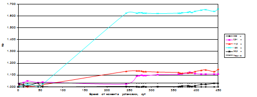
Rocks, on the section of the well between the deep benchmarks was considered destroyed if the value of relative deformation (coefficient of loosening rocks) exceeded the limit value. According to research conducted by the CIC under the direction of I. L. Chernyak the maximum relative deformation for shale is 3*10-2, and sandy shale 2*10-2
As can be seen from the data presented in pic. 2, 3, 6, 7 already on the second day of observations, the destruction of rocks in the sides of generation took place at a distance of 0.5–1.0 m, 2.0–2.5 m from the contour . In the roof of the mine working, at the same time there was a destruction of rocks at sites well removed 2.6–2.9 m and 4.1–4,7 m. At the forty-fifth day of observations, the highest values of the coefficients loosening recorded across the length of the lateral wells (0.5 to 2.5 m). In a vertical well during this period, significant deformations occur on the section of the wellbore remote from the circuit 3.5–5.0 m. To fifty-fifth day of observation of destruction of rocks in the roof continues on the same sites and extend deep into the array into sections 2,4–2.6 m and 4.7–5.0 m. further, the propagation of deformation into the array in the sides of generation, which is accompanied by destruction of breeds of a roof on a plot of vertical wells 1,5–2.4 m, in the direction of contour generation. 450 a day observing the destruction covered rocks, deleted 1.5–5.0 m from the contour in the roof and 0.8–2.5 m in boca.
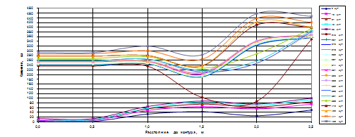
Analyzing the graphs presented in pic. 4, 5, 8, 9 you notice that on the second day of observation of destruction of rocks in the sides of generation took place at the distance of 0.5–1.0 m, 2.0–2.5 m from the contour. In the same period, in the roof of generation, destruction has occurred on sections 2,4–2.6 m; 3,5–4.4 m and 4.7–5.0 m. As shown by further observations, ongoing destruction of rocks in the sides on sites of 0.5–1.0 m and 1.5-2.0 m was accompanied by exorbitant deformation of roof rocks on sections 2,4–2.6 m and 3.5–5.0 m. At 55 days of observations, the rock at the site of the lateral wells of 0.5–2.0 m from the contour were destroyed. This has led to the destruction of rocks in the roof at the distance of 1.8–2.1 m from the contour and further loosening rocks on the already destroyed land. Ongoing intensive destruction of rocks at the sides develop at the distance of 0.5–1.0 m and 1.5–2.0 m to 450 days of observations have led to the proliferation of extreme deformations in the roof at the distance of 1.5–2.6 m and 3.5–5.0 m from the contour.
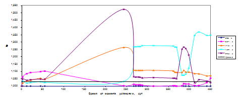
For the observation period 361–589 day shifting circuit in metering stations was as follows: from 67 to 150 mm from the side of the roof and 95–325 mm – from the sides of the excavation. Intensive displacement of rocks from the sides of the excavation led to the destruction of the racks lining and plastic deformation in coal-to-side pickups.
Conclusion
As a result of performed investigations revealed the following features of the deformation of the host rocks. Before doing cleaning work, the deformation of the contour of the excavation is not significant. The maximum displacement of the roof up to 180 mm, and the sides – up to 365 mm. overall condition is good workings. Deformation of rocks in the depth of the array is of the following character. Before the inclusion of anchors (2–8 days) destruction occur in the roof from the excavation contour to a depth of 0.5 m. Then, the dissolved species in the depths of the mountain, outside shankarananda area. Shankarananda region breeds practically destroyed, while the largest displacement of the rock outcrops in the roof of a drift is observed in the middle of the span (there's a smooth deflection), and near the walls – formed plastic hinges. At the sides develop the destruction of the formation and rocks occur at a depth of 2.5 m and are manifested in the form of squeezing the top pack of coal and rocks of the immediate layer soil. This can be explained by the presence in the sides of the weak formulation of the host rocks. In this case, the deformation is plastic in nature.
References
- Указания по рациональному расположению, охране и поддержанию горных выработок на угольных шахтах СССР. – Изд. 4-е, дополненное. Л., 1986. 222 с.
- КД 12.01.01.501-98. – Система обеспечения надежного и безопасного функционирования горных выработок с анкерным креплением. Общие технические требованиям.
- СОУП 10.1.05411357.010. – Система обеспечения надежного и безопасного функционирования горных выработок с анкерным креплением. Общие технические требования, 2007. 62 с.
- Плетнев В. А., Касьян Н. Н., Петренко Ю. А., Новиков А. О., Сахно И. Г. – Результаты внедрения анкерных систем для поддержания горных выработок на шахте
Добропольская
// Геотехнологии и управление производством ХХI века. Монография в 2-х томах. ДонНТУ, ДЦНПГО, 2006. с. 39–44. - Новиков А. О., Сахно И. Г. – Исследование особенностей деформирования породного массива, вмещающего выработку, закрепленную анкерной крепью // Известия Донецкого горного института. – Донецк: ДонНТУ, 2007. – № 1. c. 82–88.
- Новиков А. О., Гладкий С. Ю., Шестопалов И. Н. – Об особенностях деформирования породного массива, вмещающего подготовительные выработки с анкерным креплением // Известия Донецкого горного института. – Донецк: ДонНТУ, 2008. – № 1. c. 120–129.
- КД 12.01.01.201-98. – Расположение, охрана и поддержание горных выработок при отработке угольных пластов на шахтах. Методические указания, 1998. 149 с.