
Abstract
Content
- Introduction
- 1. The purpose and objectives of the master's work
- 2. The analysis is effectively applied starting nodes GBS
- 3. Problems develop new launch sites GBS
- 4. Schematic diagram of the proposed launch sites
- Findings
- List of sources
Introduction
Mineral resources development offshore due to such factors as: shortage of ore, limited or total absence of any commercial reserves minerals on land within the country, as well as the desire for independence from import the necessary raw materials.
For the development of offshore fields is necessary to drill a large number of exploration and structural maping wells in solid minerals, engineering geological wells for the design and construction of special facilities by the sea. These wells are drilled to a depth of 50 m in a small area waters. An important condition for the implementation of geological problems is the most rapid and cost-effective performance of work under difficult meteorological and hydrological sea conditions [1].
The solution to these problems is the introduction of light technical means (LTS) maximally adapted to the standard equipment of ships economical general technical purposes. That involves the development of seawater without columns flowsheet drilling wells. As well as this scheme provides for the complete exclusion of such a marker and energy-intensive equipment such as: drilling rig derrick, stations for preparation, storage and cleaning of drilling mud, and ect.
For Ukraine, the importance of the marked technological scheme is determined by the presence of sufficient the number of specialized ships (seagoing tugs, rescue vessels and others.) operational the technical possibilities which are suitable for the implementation of seawater technology drilling scheme, as well as a priority in the creation of multi-functional hydraulic hammers drill (GBS) Performance which greatly exceeds the known foreign analogues [6]
According to [2] LTS use in drilling offshore provides a high level of safety of the geological material (clay rocks of 90...100%, for the rest of the rocks in the m. h. on the sands of 88–95%), which is one of the most important indicators of quality of performance engineering and geological studies.
Technical tools used for drilling wells up to 50 meters for the better use GBS reserves implement drilling cycle, which consists of a series of repeating at its intervals of two methods of destruction of rocks:
- With coring due to frequency impact drill dive to the bottom sediments to a predetermined depth;
- Without coring due to erosion of rocks or shock jetting their destruction or to a previously traversed a given interval of the wellbore [1].
This arrangement makes it possible not to fix the walls of the well casing and thereby reduce the time and costs of the well.
At the present stage the relevance of logistics of drilling wells up to 50 m
increased and is largely determined by domestic specialized production plans
Enterprises GAO Chernomorneftegaz
and GGP Prichernomorgeologiya
, for which the emerging trend of growth
drilling volumes due to the prospect of implementation of government programs aimed at studying
Ukrainian sector of the Black and Azov Seas.
In accordance with the The development of hydrocarbon resources of Ukrainian sector of the Black and Azov Seas
(1996 year)
GAO Chernomorneftegaz
provided for the continuation of exploration works on perspective areas of hydrocarbon deposits,
as well as areas of open and operating gas fields of the Azov and Black Seas. The implementation of the planned projects
It involves a large-scale drilling of hundreds of wells 6–50 m
with the aim of engineering study of the seabed for the strength characteristics of soils that form the foundation for buildings of special marine facilities [3, 4] .
Based on the above, technical support for drilling wells up to 50 m It is highly relevant and its improvement is of great importance in the development of mineral and hydrocarbon resources of marine mineral deposits.
1. The purpose and objectives of the master's work
The purpose of the work is to develop a relationship of hydraulic parameters and rationale start-up of hydraulic components and hydraulic drill to improve efficiency the combined destruction of rocks in the technological cycle of penetration mnogoreysovoy wells up to 50 m.
Research tasks:
– justification of the scheme as a way of starting node elements of hydraulic drill, providing flowsheet mnogoreysovoy sinking wells in marine areas;
– development of a method of engineering calculation and determination of the characteristics of hydromechanical top the starting node for the sustainable state of its generating elements in a mode the combined destruction of rocks on the interval drilling without coring;
– Experimental studies of the lower starting node to select its parameters and control modes when locking and unlocking the channels flowing liquid in the core tube;
– development of drawings on an improved version of hydraulic drilling mnogoreysovogo projectile for drilling wells in offshore zones.
Object Research – technological schemes and facilities drilling wells a depth of 50 m under sea areas.
Subject Research – parameters and workflows launch sites, providing a combined method of destruction of rocks during tunneling mnogoreysovoy of hydraulic drill wells.
2. The analysis is effectively applied starting nodes GBS
In accordance with the fundamental purpose of actuating assemblies are composed of GBS supply circuit hydropercussion machines and at the same time perform the functions of a switch, with overlapping chambers hammers and the opening of channels for free passage of fluid downhole mode jetting failure precipitation.
In accordance with the standard of classification, closures launch sites hydropercussion drill include: diversion – to trigger; in design – to spring; the nature of the work: Valve – to normally open; plunger valve – a normally closed; Resources response – the pressure of the incoming fluid flow [1].
Currently, summarizing the criteria development triggers CBE, is the nature of fixed position starting nodes according to the flow of fluid in the hydraulic system (Q). On the one hand, it ensures the supply TLU nominal quantity of water (Qnom) only of hydraulic mechanism. This NPU closes the flow of water in Coeur nopriemnuyu pipe and simultaneously transmits the waste in hammers fluid in the annulus (work mode coring). On the other hand (in the washout phase) – CPG excludes access large amounts of water (Q1) in working chambers hammers while NEC directs the entire flow of liquid (Q1>Qnom) in core tube, and then through the core catcher a nozzle downhole [4].
3. Problems develop new launch sites GBS
According to [1], the operation of the PBS-127 as part of the UMB-130 and UMB-130M on board SO/SSN
Neftegaz 68
in the gas fields Black Sea shelf for drilling wells with complex
geological sections had difficulties due to violation of the conditions of synchronous operation
AAMS upper and lower start-up units in the range of liquid flow Q...Q1.
When laid ratios of engine parameters of hydraulic mechanism PBS-127, value of impact energy (E) and the frequency of attacks (n) to break, primarily occurring on section of the wellbore sawmills, provided at the increased flow rates.
In the literature [4] affirms that technologically favorable with robust counter-lemma condition shut-off and regulating systems VPU-II and NPU-II is to comply with the ratio Qcp0.3Q. For the forced functional modes of the received performance hydraulic PBS-127, recommended value It suggests the need for the condition Qf>400 l/min. Given the limitations of the ship energy, the use of such a level Qf, which is a factor in increasing the power of the pump drive, It is difficult.
Therefore, the sum of tasks related to the development of CPG was complemented questions parametric optimization of hydraulic mechanism, to adapt it to the drive characteristic Cams most apply the mud pumps, subject to the conditions: Q sr0.3 and Qf=300 l/min.
The fundamental nature of the problem are caused by the need to improve kinematics and making profitable construction of the "VPU-hydraulic mechanism-NPU". This mechanism of hydraulic, the most studied and worked in the choice of the scheme, kinematics and design node system can be regarded as a base for the development of the structure submersible drill. The least studied and are unprepared for the operation starting components of the drill, which are functionally forming elements for of the scheme mnogoreysovogo drilling wells.
The paper [5], marked the low reliability of control nodes launchers due, First of all, the imperfection of their design and the lack of evidence-based recommendations selectable range boundaries of fluid flow required for operational process control switching nodes in the phase lock or unlock hammers. Consequently, does not exclude the case of uncontrolled operation, first of all, the lower the starting node to the phase coring, especially in the areas of penetration of solid ground, with increasing frequency and energy parameters hammers increase the pump. This led to the opening of access of fluid in core tube, which in turn disrupt the structure of the core, or completely washed away from his core tube. As a consequence, geotechnical borehole problem was not solved.
Therefore, the task of expanding the appointment of indicators involves the development of new facilities technical proposals, aimed at a more complete implementation of hydraulic hammers drill and determine the principles of scientific and engineering problems related, first of all, ensuring high reliability launchers nodes as element determining the possibility of mnogoreysovogo drilling wells.
The most urgent task becomes associated with the creation of the CPG and NEC, precluding the need for application of the "pecking" method of penetration hole intervals and non-structural elements drill. In this regard, it can be considered as a promising direction connected starting with the development of nodes with auto platoon at multiple remote ways to incorporate them into the desired operating mode. Triggering launch sites in phase coring must occur at increased flow rates, while reducing the load on hydromotor hydropercussion machines without reducing the liquid supply in the well.
At a sufficiently high degree of reliability of launchers developed nodes drill GBS-127 and the relative ease of obtaining reasonable performance tuning for their operation at locking and unlocking hammers, technical implementation and technology of full-hole drilling solid rock is not perfect. In the long term, the development should be considered, requiring no Only a new approach to the design and selection of the control circuit starting node ZRS structure GBS, but also radically change the nature of the destruction of rocks.
Analysis of the research and practical results of the completed research given in [1] We have shown that an effective alternative beskernovoy penetration slots can serve well the way based on the use of jetting effect in combination with continuous frequency shock loads on the bottom, emerging of hydraulic mechanism.
These moments are aiming to create a universal starting construction site,
providing permanent job hammers throughout the cycle of penetration
with the ability to quickly and efficiently unlock the mechanism to coring stage.
The first task is to get experience in implementing the design of the drill GBS-108
developed on the basis of terms of reference GGP Prichernomorgeologiya
.
4. Schematic diagram of the proposed launch sites
Designed shell GBS-108 (Figure 1) is made with a single set of coring length 2,5–3 m and freely placed inside the plastic liner 10, having an internal diameter of no more than 88 mm.
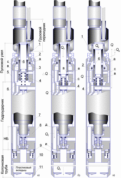
Figure – 1 Schematic diagram of hydraulic drill GBS-108.
Design and engine parameters conform to hammers for GBS-127. A distinctive feature of the development is the use of the structure of the new GBS Universal starter unit (UPU) that provides standing in the unlocked state hammers technical possibility of penetration beskernovoy previously passed or given section of the well by operating simultaneously jetting frequency and power loads, formed on the bottom of the well when running hydropercussion machine.
UPU camshaft located in the cylinder and the adapter 3 comprises two structurally interconnected elements: tube 2, spaced along the length of radial channels (b) and (c) and a spring-loaded plunger valve orifice 4 (c).
In the destruction of the rain pipe beskernovogo fixed pins 1. The flow rate Qf is set at 300–320 l / min. The incoming flow valve plunger 4 moves down (Fig. 1b). Through holes (c) in the working chamber of the fluid directed hammers Q, allowing it to run and work. Simultaneously, through the released opening (a) and radial channels (f), the share of liquid Qsr=Q1–Q enters the annular gap between the casing 5 and 6, and then, through the channels (d) bottom anvil 8 is guided in a spring-loaded check valve cavity 9. The hydraulic power of the incoming flow valve 9 moves downward, opening the window (s). Liquid in an amount of Q1 enters the core tube 10 and further through the nozzle onto the shoe 11 into downhole.
To go to the mode of coring in the hydraulic fluid supply increases to Q a=380 –400 l/min Cutoff for locating pin 1. The process is accompanied by a shift of the nozzle 2 and then down blocking the channel (c) and bores (c) dividing the opening window (s) through which runs discharge of the liquid Qa.sr=Qa–Q in the hole.
With control valve hydraulic hammer is displayed on the dive mode is effective core set into the rock at a nominal or forced flow Q, with the increased intensity of the flow of GBS due observance of the conditions Qa>Q.
Inclusion of GBS-108 check valve 9, precludes fluid suction cavity of the striker 7 during operation of the pump unit, and prevents cavity hydropercussion Mechanism of sand and sludge particles during the descent of the projectile into the well. The principle of operation of the device depicted in Figure 2.
Figure 2 – The principle of operation of the device
Figure animated. volume – 91 KB.; the number of frames – 5; the delay time – 0,4 s.; reps – indefinitely.
Findings
Presented and substantiated the scheme and the parameters of existing launch sites hydropercussion drilling shells for drilling offshore.
In the process of implementation of the master's work developed the changed structure starting nodes that provide faster and more rational sinking wells and sampling.
The greatest benefits of the new solution is reached as a result of exclusion from the drilling cycle pecking
beskernovoy way penetration areas and dense hardwood with a more rational
way of destruction of rocks, as both formed on the bottom of the well and jetting
frequency power loads during operation of hydraulic mechanism.
In addition, significantly improved the reliability of the control operation of the trigger assembly in full unlocking hammers in phase coring.
In writing this essay master's work is not yet complete. Final completion: October 2015. The full text of work and materials on the topic can be obtained from the author or his head after that date.
Список источников
- Калиниченко О. И, Хохуля А. В., Зыбинский П. В., Каракозов А. А. Установки для бесколонного бурения скважин на морских акваториях. – Донецк: «Світ книги», 2013. – 163 с.
- Новые возможности и продуктивность легких гидроударных установок для бурения инженерно–геологических скважин на морских акваториях // Калиниченко О. И., Хохуля А. В., Комарь П. Л., Тельбиш М. Ю., Мартыненко И. И. // Сб. научн. трудов. – Вып. 15. – Киев: ИСМ им. В. Н. Бакуля НАН Украины, 2012. – с. 120–125.
- Возний В. Р., Голубков С. В. Освоєння шельфу – нафтогазове майбутнє України. // Науковий вісник Івано-Франківського технічного університету нафти і газу 2(11). 2005. – с. 56–58.
- Калиниченко О. И., Зыбинский П. В., Каракозов А. А. Гидроударные буровые снаряды и установки для бурения скважин на шельфе. – Донецк:
Вебер
(Донецкое отделение), 2007. – 276 с. - Калиниченко О. И., Хохуля А. В. Основные проблемы и пути совершенствования техники и технологи многорейсового бурения скважин на морских акваториях // Науковий вісник. №7, Національного гірничого університету. Науково технічний журнал. Дніпропетровськ, 2009. С. 45–50.
- Фальков И. М., Бабич В. А., Хамидуллин Р. Г., Лисагор О. И. Современное состояние техники и технологии морского инженерно-геологического бурения // Труды ВНИИморгео. Обзор. – Рига, 1986. – 152 с.
- Калиниченко О. И., Каракозов А. А., Зыбинский П. В. Разработка погружных гидроударных снарядов для бурения подводных разведочных скважин со специализированных плавсредств // Сб. научн. трудов. – Вып.8. – Киев: ИСМ им. В. Н. Бакуля НАН Украины, 2005. – 180 с.