
Abstract
Content
- Introduction
- 1 Theme urgency
- 2 Observing rolling mill process
- 2.1 Rolling production. General definitions and concepts
- 2.2 Classification of processes of rolling
- 3 Analysis of high-speed modes of operation of electric drives of continuous rolling mill group
- 4 Aftermath of inaccuracy settings for speed modes of electric drives
- 4.1 Excessive bending force
- 4.2 Excessive tensile load
- Goals and objectives master's project
- References
Introduction
The presence of longitudinal forces in the rumblings between adjacent stands
to continuous hot rolling mills are the result of
it is not exposed to and / or supported by the right
the ratio of the drive motors speeds. This leads
to the fact that the rolled material is subjected to
uncontrolled deformation and process starting to be
unstable and is in danger zone of failure, for example
drilling
or damage to equipment.
1 Theme urgency
The development of rolled production processes in the areas of flexible high-speed technological schemes, while tightening the requirements for quality performance profiles (primarily, accuracy) makes it relevant to complex tasks for finding effective methods of targeting technological process factors.
Keep in mind the increasing development and application of process control systems, which requires a relatively simple, versatile, fast, easy and reliable model, supplemented, meeting the requirements of object-oriented software. However, the ambiguous relationship of many technological parameters of rolling in calibers varying complexity limits the development and implementation of complex systems analysis and management with high-quality rolling. The implemented system are highly specialized, do not always agree with each other, poorly adapted to the changing technological conditions of production, does not allow a rapid analysis of alternative technological schemes. Therefore adaptivity is should be considered in two aspects [3]:
- Models and systems adaptability to different processing circuits pressure shaping of metals (particularly profiled rolling) and changing conditions of pressure shaping of metals;
- Adaptability to specific technological problems.
2 Observing rolling mill process
2.1 Rolling production. Common definitions and concepts.
Rolling – process of plastic deformation of bodies on the rolling mill between the rotating driving rolls
(the part of rolls can be not driving). Words driving rolls
mean that the energy necessary for deformation
implementation is transmitted through the rolls connected to the engine of the rolling mill. The deformable body
can be stretched also through not driving (idle) rolls, but it will be not process of rolling, but drawing process.
Rolling is among the main ways of processing of metals pressure. Rolling receive products (rolling) of a various form and the sizes.
As well as any other way of processing of metals pressure rolling serves not only for receiving the necessary form of a product, but
also for formation at him a certain structure and properties [6].
2.2 Classification of processes of rolling
Processes of rolling classify by the following signs [6]:
- on temperature of carrying out process rolling is divided on hot (metal temperature at realization of process higher than recrystallization temperature) and cold (temperature of metal is lower than recrystallization temperature). Also so-called warm rolling – processing in the field of intermediate temperatures takes place;
- on a relative positioning of axes of rolls and strips distinguish longitudinal (an axis of the rolled strip perpendicular to axes of rolls), cross (the axis of the rolled strip is parallel to axes of rolls) and cross and screw or slanting rolling (axes of rolls are under some corner to each other and to an axis of the rolled strip;
- on nature of impact of rolls on a strip and deformation conditions rolling happens symmetric and asymmetrical. Symmetric rolling call process at which impact of each of rolls on the rolled strip is identical. If this condition is violated process it is necessary to carry to asymmetrical;
- on existence or lack of the external forces applied by the ends of a strip allocate free and not free rolling. Rolling is called free if the strip is affected only by forces applied from rolls. Not free rolling is carried out with a tension or a podpor of the ends of a strip.
3 Analysis of high-speed modes of operation of electric drives of continuous rolling mill group
Metal rolling refers to metal forming by pressure. The method consists in changing geometric dimensions of roll during the passage between the rotating shafts. As a result, increases the rolling width and length of the metal.
During metal forming it is assumed that the volume of the body during plastic deformation remains permanent. This makes it possible to link the size of the body before deformation with body size after deformation.
Formulates the law of constancy-second volume in the following way: the volume of metal flowing per unit time through the certain cross section deformation zone, which is formed by the working tool, it does not change when passing from one section to another in a continuous processing mode.
Mathematically, the law of constancy-second volume is expressed by:
where Vi – average speed of movement of the metal in the i-th cross-sectional area of the deformation zone Fi [1].
On the basis of this law establish the relationship between the speed of movement of the metal and changes cross-sectional size of the deformable substrate in continuous processing mode.
Figure 1 is a technological scheme of metal rolling in a six-stand mill, consisting of a series alternating horizontal and vertical stands [2]. Such technological scheme is designed to form the desired product profile in height and width.
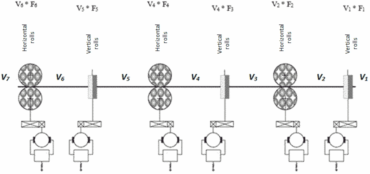
Figure 1 – Structural scheme of metal forming by pressure
Figure 1: Wi*Fi – law of conservation of second-volume of metal in the stands;
Vi – linear speed of metal;
Fi – sectional area of the deformation zone;
Vi & ndash; the volume of metal in interstand space.
Speed management of the main drives of the rolling stands is one of the main functions of automated process control system (PCS) of continuous rolling mill. Its task - for given strip speed at the exit of the final stand, based on the mode and compresses law constancy Seconds volumes strip speed calculated in each stand, and then, based on advancing, to identify and select a speed of rotation of the rolls. Its task - for given strip speed at the exit of the final stand, based on the mode of compresses and law constancy second-volumes, strip speed calculated in each stand, and then, based on advancing, to identify and select a speed of rotation of the rolls [2].
The cross section of the deformation zone Fi area is defined by the calibration of rolls of the stands, so the linear velocity of the electric drive must be strictly maintained in accordance with a change in cross-section passing metal.
Requirements to the drive of rolling mills:
- wide margin of speed control;
- high overload capacity at the torque;
- good operational reliability;
- minimum inertia;
- high starting torque;
- rigid mechanical characteristics.
In strict observance of speed limits by means of the electric drive, the metal will be rolled freely. An indication of compliance with free-rolling conditions can be static electric current of the first stand. If he hasn't changed after metal capture by rolls of the subsequent cage at simultaneous rolling in two cages, then rolling goes freely – there are no efforts of extension or tension. At change of static current of the ED of the first cage in the big party there is a redistribution of loading – the first cage assumes part of loading of the following cage. At the same time there is an effort of extension in a inter-stand interval. For his elimination it is necessary or to increase the angular speed of the drive of the second cage, or to reduce the angular speed of the first.
If static current of the EDS of the first cage has changed in the smaller party, therefore, the following cage has assumed part of loading of previous. At the same time there is an effort of a tension in an inter-stand interval. For his elimination it is necessary or to increase the angular speed of the previous cage, or to reduce the angular speed of following.
The sequence of correction of speeds can be both on the rolling process course, and against him:
- Correction of speed on the course of rolling process is carried out by method of fine tuning of subsequent (i+1)-th cages under the previous i-th cage. That is, change the angular speed of rotation of rolls (i+1)-th to a cage in relation to cage i-th.
- Correction of speed against the course of rolling process means change of angular speed of rotation of rolls of the previous i-th cage in relation to the speed of rotation of rolls of subsequent (i+1)-th cage.
4 Aftermath of inaccuracy settings for speed modes of electric drives
4.1 Excessive bending force
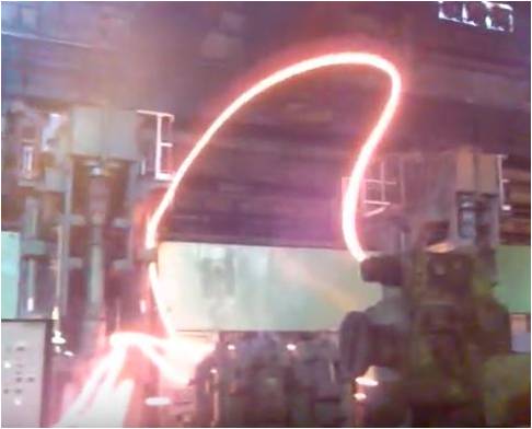
Figure 2 – Consequences of excessive effort of extension in metal on an inter-stand interval
Figure 2 – Consequences of excessive effort of extension in metal on an inter-stand interval
The result of excessive effort of extension is drilling, i.e. the rolled metal has not come into the following cage and has begun to be bent. For avoiding of consequences of drilling, as a rule, using a special device for catching metal. In case of their absence damage to machinery, postings is possible, and there is also a threat of life of service staff.
4.2 Excessive tensile load
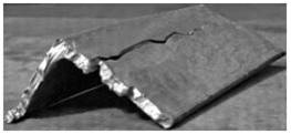 Figure 3 – Tension crack |
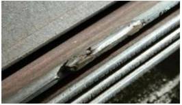 Figure 4 – The deformation |
The consequences of excessive tensile force may be several events.
The crack of tension and deformation gap
are defects of rolling process and owing to them the rolling mill receives defective products.
Tension crack (figure 3) appears, as a rule, when rolling a corner. It arises at worn-out working rolls because of which the effort of compression enclosed to metal, unevenly on all its area. In other words, working rolls roll one party of a corner quicker, than another.
The deformation gap
(figure 4) arise at sharp acceleration of rotation of working rolls
of a cage at metal capture. Actually, there is a slipping and metal is getting licked
.
Goals and objectives master's project
Taking into account everything is higher stated, in the degree project it is planned to choose the most rational control algorithm of the high-speed control modes and to consider the possibility of realization of automatic system of regulation of angular speeds of working rolls for draft group of the continuous rolling mill 390 of the Makiivka branch of Yenakiieve iron and steel works. Also, in system of regulation of angular speeds of working rolls for draft group compensations of efforts in metal in inter-stand intervals have to be considered [7].
Objectives master's project:
- To make the analysis of a advantages and disadvantages of the existing system of regulation of angular speeds of working rolls of the rolling mill 390;
- To offer several alternative options of algorithms of creation of automatic system of regulation;
- To make the block diagram of the chosen algorithm of regulation;
- To write the program of automatic control in software packages (Matlab, Simatic manager);
- To provide proofs of feasibility of the project on mathematical model.
At the time of writing this abstract of master's work is not yet complete.
The estimated date of completion of the master's work: June 2017. The full text of work and materials on the topic can be obtained from the author or his manager after that date.
References
- Теория обработки металлов давлением: Конспект лекций и варианты заданий для выполнения курсовой работы / сост. Н. Н. Загиров, Э. А. Рудницкий. - Красноярск: Сиб. федер. ун-т, 2011. - 5 стр.
- Pазработка математической модели взаимосвязанных электромеханических систем черновой группы прокатного стана. Андрюшин И. Ю., Шубин А. Г., Гостев А. Н. / Электротехнические системы и комплексы. Вып. № 3 (24) 2014 г. - С 24–30.
- Тулупов О. Н., Способ задания скоростного режима непрерывной группы прокатных клетей стана горячей прокатки металла с обеспечением минимального натяжения в межклетевых промежутках: Обработка металлов давлением. д-р технич. наук. Магнитогорский гос. техн. унив. им. Г.И. Носова, Магнитогорск, 2001 г.
Режим доступа:Техносфера
– библиотека технических наук. - Бурьков В. В., Юнгер И. Б. - Способ задания скоростного режима непрерывной группы прокатных клетей стана горячей прокатки металла с обеспечением минимального натяжения в межклетевых промежутках, 2007 г.
Режим доступа:FindPatent.ru
– патентный поиск, 2012-2016. - Цены на готовую продукцию компании
КТ-СТАЛЬ
.
Режим доступа: База металлопрокатаКТ-СТАЛЬ
. - Редакционная статья, прокатное производство, 2013 г.
Режим доступа: Международное изданиеMetallurgical and Mining Industry
. - Шубин А. Г., Гостев А. Н., Храмшин Р. Р., Одинцов К. Э. – Исследование системы компенсации межклетевых усилий в черновой группе прокатного стана методом математического моделирования // ЭС и К. 2015. № 4 (29).
Режим доступа:КиберЛенинка
– научная электронная библиотека.