
Abstract on the final work
Content
- Introduction
- 1. Relevance of the topic
- 2. The purpose and objectives of the study, expected results
- 3. Overview of international sources
- 4. The kinematics and dynamics of the robot
- 4.1 The kinematics of the manipulator
- 4.2 The dynamics of the manipulator
- 5. Modeling
- Conclusions
- List of sources
Introduction
The most important functional element in ensuring the stability of the processes of the metal movement in the mold of CCM, is a submerged nozzle. Through technological overflow of the liquid metal at the site tundish-mold
, it carries metal protection functions from the secondary oxidation of the melt supply to the level in the mold, facilitating traffic management convective flows in a liquid bath, as well as the prevention of pollution was the inclusion of slag-forming mixtures placed on the the meniscus.
1. Relevance of the topic
In modern practice, the continuous casting slab blanks becoming increasingly widespread technique rapid replacement of the submerged nozzle. The feasibility of such a replacement is determined by the ability to exclude metal waste from slag zones, which are formed in the operation of conventional products. This replacement is achieved by using a special device, installed under the bottom of the ladle and providing rapid movement of submerged nozzles (old and new) along the slip plane. Replacing the submerged nozzle is carried out within one to two seconds, which does not disturb the normal course of the casting process (does not change the position of the head of the stopper, does not stop operation of the system of automatic control of metal level in the mold, etc. ).
2. The purpose and objectives of the study, expected results
In this process focuses on the mechanism of rotation and flow manipulator glass. For starters expected to perform analysis of modes of the device, select the drive motor and the drive system. Develop a mathematical model in Matlab/Simulink environment. Further experimental studies are anticipated to produce, and to identify the main strengths and weaknesses of the used drive. At the moment, the questions the behavior of electromechanical system based on its model based on the elastic properties of the manipulator in the intermediate cup installation mode, shows the sequence of the selection units of the manipulator and the determination of their elastic properties. It is assumed idealized two-mass system in which the damping properties are accounted for on the basis of viscous friction.
3. Overview of international sources
The first industrial robots appeared in the US in 1959, when the robots have been created with program management. In 1962, the use of robots found their Yunimeyt
, Versatran
for maintenance of casting processes, forging, machining, spot welding, painting. The cost of the first robot was 25–30 thousand dollars per unit. In the automotive and steel industry payback period was 1.5–2.5 years, which was quite high for the time [1].
It is interesting to note that in MeshineriMegezin
published an article about a new type of worker who does not drink coffee or smoke, is open 24 hours a day and is not a member of a union [4].
The word robota
(corvee, forced labor) was used by the Czech writer Karl Capek in the play RUR (Rossum Universal Robots, January 1921).
It quickly migrated to the technique and has been used as a common noun for those mechanisms that perform heavy, monotonous work. This mechanism class and was named robots
.
The advanced countries of the world are beginning to release the active IR in the struggle for rynkisbyta. In the first place in the design, manufacture and implementation beyond Japan. The dynamics of growth in output IR can be seen in the following figures: in 1978, there were 16,000 PR, in 1980 in the world – 25,000 in 1983 – in the capitalist countries – 31000 pieces.
According to this indicator, the number of robots per 10,000 workers in the first place in the world, Sweden – 40, Japan – 13, in the United States and Germany – 3–4 pcs.
According to preliminary data of the Soviet Union in 1983 there were about 7,000 industrial robots, and by 1990 it was planned to increase the number of robots to 375 thousand units.
Japan continues to hold the championship for the design of new types of robots. Much attention is paid to the creation of so-called humanoid robots, repeating human movement, designed and manufactured specialized robots to help people with impaired hearing, the musculoskeletal system [1, 2].
4. The kinematics and dynamics of the robot
Study kinematics and dynamics is an important step in the design of manipulators. At this stage the docking modules designed geometric characteristics and degrees of mobility in general manipulator with a working space and a working area of the robot; determined from the standpoint of possibility of manipulator kinematics and dynamics in the performance of certain manufacturing operations; taken into account the various adverse factors, such as elastic yielding elements. The results of these studies are commonly used to adjust the design decisions taken at previous stages of the design. In addition, they are needed in the future in the design of the robot control system, since their base is constructed as a model of the robot control object [3].
4.1 The kinematics of the manipulator
For the formulation and solution of problems of Kinematics typically calculated kinematic manipulator model, which is based should be based on existing or prospective geometric dimensions of the units, as well as the types, amount and distribution of kinematic pairs. The manipulator typically is an open kinematic chain elements which are connected to each other by means of kinematic pairs. As a rule, it odnopodvizhnye kinematic pair of fifth grade – rotational or translational. If the kinematic chain contains no internal closed circuit, the number of pairs of kinematic m defines the number of degrees of mobility of the manipulator. Simple controllers have two or three degrees of freedom. Universal, as well as some special manipulators mogutimet six to eight degrees of mobility, links of the kinematic chain connected by kinematic pairs so that one of them is attached to the base (mobile or fixed), and another bears the actuator - gripper or tool.
The position of the kinematic chain in the space will be determined using the generalized coordinates qi(i=1,2,...n), characterizing the relative movements in the kinematic pairs. To determine the working body position in space we introduce coordinates rj(j=1,2,...m), where m≤6. In general m=6, i.e. must enter the six scalar quantities, such as the three coordinates of a point seized, taken as a pole, and three corners that characterize the orientation of the coordinate system rigidly connected with Tong, relative to a reference coordinate system associated with the base. We look at some of the most typical problems of kinematics of manipulators. Direct problem of manipulators position.
In this task calculates the position of the working body and the manipulator links by specified relative movement qi(i=1,2,...n). There are three options for setting the direct problem. Coordinates qi(i=1,2,...n) can be set:
- as a set of n scalar values that define some fixed configuration of the manipulator;
- in the form of a finite number of sets corresponding to several configurations;
- as a set and continuous functions of time qi=qi(t)(i=1,2,...n);
With the help of the direct problem can be determined:
- the geometric characteristics of the working space and work area manipulators with complex kinematics with the structural limitations on the type of generalized coordinates qi min≤qi≤qi max(i = 1, 2,... n);
- precision characteristics, such as error Δrj(j=1,2,...,m) positioning the gripper rj(j=1,2,...,m), caused by inaccurate manufacturer manipulator elements, or errors Δqi(i=1,2,...,n);
- working out the relative movements qi(i=1,2,...,n) in kinematic pairs;
- service characteristics.
The direct problem of the position used in the study of kinematics and dynamics of manipulators.
An inverse problem of the position of the manipulator. With this task determine generalized coordinates qi(i=1,2,...,n) manipulator for a given in the reference coordinate system, the position of the working body or a link manipulator. In particular, if the specified coordinates gripper rj(j=1,2,...m) possible to determine the generalized coordinates of the manipulator qi(i=1,2,...,n), the coordinates of the other links of the manipulator are at the next stage by solving the direct problem.
Conditions n=m is necessary to inverse problem generally have a solution, that is, to be able to create n independent equations with n unknowns. In some cases, when n = m-making may be a few. As an example, Figure 1 shows a flat trehzvennik hinge with three degrees of freedom (n=3). Position gripper as a rigid body is determined by three coordinates in the plane: coordinates xp и yp pole gripper P and the angle α between the coordinate system rigidly connected with gripper Рx’у’ and the reference Оху (m=3). If on generalized coordinates q1, q2 и q3 not imposed restrictions, it always has two configurations (second in Figure 1 is shown by the dotted line) to ensure a predetermined position gripper. In this case we say that the manipulator has one degree of maneuverability. Which of the solutions should be chosen depends on the conditions, such as obstacles in the working space of the manipulator or design constraints on the generalized coordinates, which for real manipulators always occur.
Condition n=m is not sufficient, so there may be options when the inverse problem solution is not available (it depends on the type and distribution of kinematic pairs). In this case, you must reduce the number of t arbitrarily defined coordinates gripper. May exist specific solutions in which some of the generalized coordinates qi, allowed any value.
When n<m the solution of the inverse problem in general is absent. It can be obtained, if only arbitrarily set n gripper coordinates.
When n>m the inverse problem is solved ambiguously. If, for example, are given t gripper coordinates rj(j=1,2,...,m), in the general case, you can still freely set the n-m generalized coordinates qi. The remaining m generalized coordinates qi, found from the solution of the inverse problem of the situation. При n>m it says that the manipulator has a redundant degree of mobility. Their use enables the manipulator ability to work in an environment with obstacles, as well as consider additional restrictions on generalized coordinates qi(i=1,2,...,n) or the terms of the configuration of the manipulator.
As a direct problem of manipulator position in the inverse problem of setting three options:
- given by one position gripper, that is, one set of scalar values rj(j=1,2,...,m) and, accordingly, there is one configuration of the manipulator (or multiple configurations, if there are several solutions);
- given a finite number of provisions of gripper and manipulator configuration are appropriate (for some positions gripper multiple configurations can be found);
- given law gripper movement over time rj=rj(t)(j = 1, 2, ...m) and changes in laws are generalized coordinates qi=qi(t)(i = 1, 2,.. n).
The inverse problem of manipulator position is more complicated than a straight line. In many cases, it can be effectively solved only numerically.
The problem of calculation of linear velocities and accelerations of the manipulator some points, and angular velocities and accelerations of its links. This problem is closely connected with the direct and inverse problem of the manipulator position and may also have direct and inverse statement [3].
Figure 1 – Hand manipulator with three degrees of freedom (animation: 4 frames, 7 cycles of repetition, delay 2000 ms, 69 kilobytes)
4.2 The dynamics of the manipulator
In the study of the dynamics of manipulators make estimated dynamic model takes into account not only the geometric dimensions of the units and the distribution of kinematic pairs as in the preparation of the kinematic model, but also the distribution of the masses of links and other elements of the manipulator involved in the movement. It may be included, and other properties of the manipulator, such resilient properties of its elements. In this case the number of degrees of freedom of the system is greater than the number of degrees of mobility of the manipulator, which is defined as the number of independent controlled motions of the manipulator (for manipulators with open kinematic chain is equal to the number of drives).
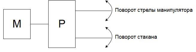
Figure 2 – A simplified diagram of the transmission of motion from the engine to the links
5. Modeling
Viewed manipulator can be presented estimated electromechanical system consisting of two principal masses. The first estimated weight includes engine components and mechanical drive. The second mass - a gripping device with an intermediate glass. Between these units are hand that the stiffness is taken into account. I. e. real circuit design can be reduced to the form (fig. 3)
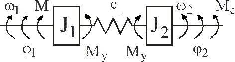
Figure 3 – Diagram of a two-mass system
Power drive motor is generally performed on the managed converter (both DC and AC possible). View the desired mechanical characteristics and dynamic nature of the time can be implemented for any of the above systems. I. e. research the system behavior can be performed in a first approximation on the basis of changes in the nature of dynamic torque acting on the first weight calculation system.
The account of the elastic properties of the system is made in modeling the latest. The system of equations describing its behavior are listed below [5-7].

Mathematical model for the reduced system of equations is presented on fig.4.
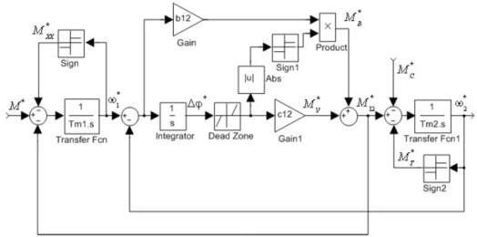
Figure 4 – Mathematical model of a two-mass system
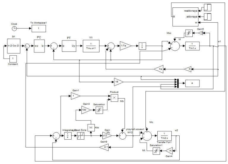
Figure 5 – Mathematical model of electromechanical intermediate glass installation
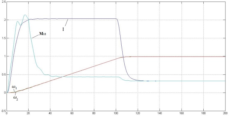
Figure 6 – The nature of change in current, the elastic moment and calculated the mass velocity
Conclusions
In this lecture it was considered robotic complex to replace the glass in the area tundish-mold. study the kinematics and dynamics of the manipulator was carried out to correct design decisions taken at previous stages of the design. The mathematical model two-mass systems based on DC motor. As can be seen from the calculated waveforms of the system start-up is accompanied by slight fluctuations that money had eventually lead to interference when installing glass in the guide.
List of sources
- Процессы непрерывной разливки / А. Н. Смирнов, В. Л. Пилюшенко, А. А. Минаев и др. – Донецк: ДонНТУ, 2002. – 536 с.
- Springer Handbook of Automation / Ed. by S. Y. Nof. – Berlin: Springer Verlag, 2009. – 1812 p. – P. 450.
- Учеб. пособие для студ. вузов, обучающихся по спец.
Робототехнические системы
/ С. Ф. Бурдаков, В. А. Дьяченко, А. Н. Тимофеев – М.: Высш. шк., 1986 г. – 264 с. - Введение в специальность. В. Ф. Борисенко, – Донецк, ДонНТУ, 2014. – 357 с.
- Двухмассовая модель механической части силового канала электропривода [Электронный ресурс] – Режим доступа: http://studopedia.ru/.
- Учебные материалы для студентов [Электронный ресурс] – Режим доступа: http://vunivere.ru/.
- Синтез математической модели двухмассовой электромеханической системы/ И. А. Орловский, И. В. Блохин – ЗНТУ, Украина, 2011.