
Abstract
Table of contents
- Introduction
- 1. Crane modeling in Comsol Multiphysics
- 2. Overview of the modeling results
- Conclusion
- References
Introduction
Modernization of crane mechanism is an urgent task now. Automation processes and improvement equipment reduce energy consumption and increase efficiency by reducing cycle time for moving loads.
The characteristic feature of extent constructions is distribution of their mass and rigidity along their length. In this case elastic vibrations are described by differential equations in partial derivatives, solved by the method of finite elements. That is why, nowadays, for the solution of such problems specialized program packages, oriented on studying the objects with distributed parameters, are often used.
The model of the traveling crane comprises two crossbars, fixed on the edges of platforms. To platforms applied force equal to the force of moving the crane drives. Position the trolley chosen as the middle. The cart is made in the form of a platform to which a suspended load. It should be noted that the weightof the model is approximately equal to the mass of the real overhead crane.
1. Modeling crane in Comsol Multiphysics
For the modeling processes in mechanical systems in Comsol Multiphysics package is Multibody Dinamics module, containing a variety libraries designed for modeling systems.
Creating the model in the program is as follows.
.- You must specify dimension space graphic 3D, 2D, 1D.
- Specify area study physical phenomena and type problem to be solved, such as static or transient, natural frequencies, and others.
- The build geometry of the object, which has a graphical interface and Geometry is also possible to import models created specialized image editors.
- Specify the properties of the material construction structure, for that Librarie s are provided Materials. Expansion of "Material Library" contains over 2 500 materials and tens of thousands of features and functions, depending on the temperature.
- Group the elements of design and identify the relationship of these elements (rigid connection, flexible, various types of connections, joints).
- Specify the physical properties of the object, which has a graphical user interface Physics.
As an example, consider the process of creating a model crane (see. Fig. 1). We will assume as a basis the data of the travelling crane 10-5К-20-10 У2.
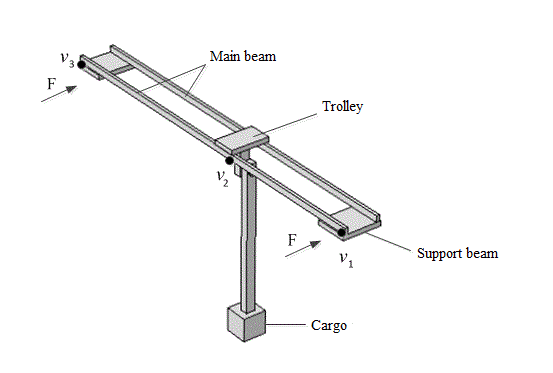
Figure 1 – Model of travelling crane.
2. Overview of the simulation results
The accuracy of modeling results, obtained from this model, will depend on the degree of correspondence of model geometry to real dimensions of the installation. It should be taken into account, that availability of small pieces in the construction leads to considerable increase of the volume of machine memory, needed for computations. That is why, it is expedient to realize the construction in the form of the set of beams, section of which corresponds to the dimensions of the considered crane. In this case the mass of construction drastically increases, that is why it is necessary to reduce density and rigidity of the material, it is made of. Besides this, modeling of the process of load rocking and lifting is rather complicated, due to the lack of the possibility to create articulated joints and flexible rapes, and realization of trolley motion across the bridge is connected with certain difficulties. That is why, we will be limited by one charging trolley without load, rigidly fixed at a certain point of bridge construction. Neglecting the elasticity of the contact between the rail and the wheel, we may assume that the beams of the crane cannot move in transversal direction and in vertical direction, that is realized only by means of prohibiting of travelling of low sides of supporting beams. Force, produced by drive motors, can be realized, applying the equivalent by its value, force to the extreme sides of supporting beams in the direction of bridge travelling. The action of gravitational force can be taken into consideration, introducing the force, distributed along the while volume of the construction, calculated as F = gρ, where ρ – is the density of the material.
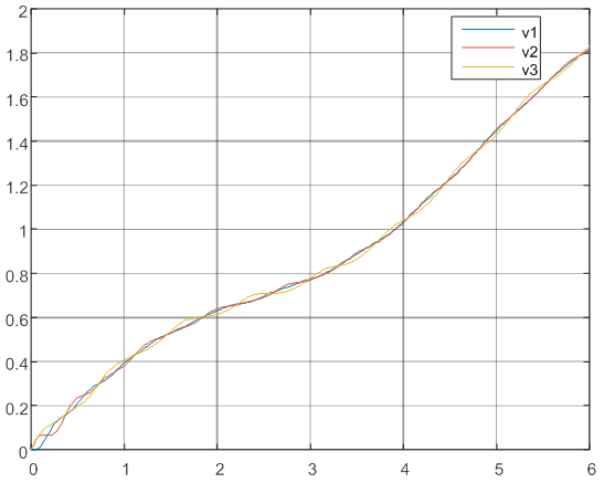
Figure 2 – Graph speed points v1, v2 and v3 from the time
The graph shows the change in velocity movement of the crane in points v1, v2, and v3. Points v1 and v3. located on the edges of the crane beams, and the middle point v2. Because speed is almost the same, it would be appropriate to submit a speed schedule. Chart speed difference is shown in Figure 3.
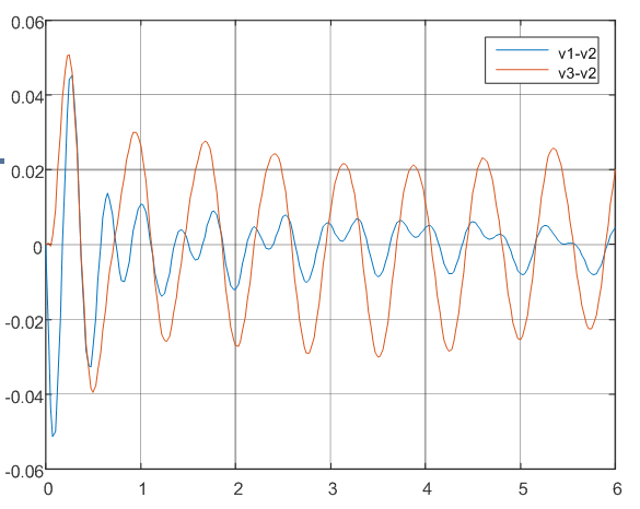
Figure 3 – Dependence of the velocity difference v1, v2 and v3 on time
The graph shows the pronounced fluctuations in load and design. The first portion v1–v2 expressed two frequencies, the frequency fluctuation of construction and the oscillation frequency of cargo in the second region v2–v3, traced the same frequency, but with higher amplitude is due to the fact that the coefficient of rigidity in this lower portion.
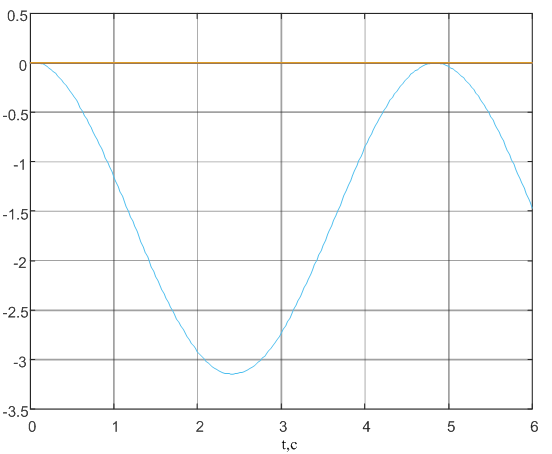
Figure 4 – Graph offset angle cargo
The graph shows that the fluctuation of the load at the beginning of the movement is about 3 degrees. The frequency of oscillation of cargo in line with expectations. Pendulum at movement with constant acceleration swings only in one half-plane, the same we see on the chart.
Thus, the developed model allows the study the elastic structure of crane fluctuations.
Conclusion
The horizontal movement of the crane with trolley, fixed in a point, with a sufficient degree precision modelled in the Comsol Multiphysics. This model allows to synthesize the controller speed for the effective the decrease in oscillation his construction. Further research will with into account the movement of the truck with suspended to it cargo.
Final end: May, 2017. The full text of work and materials on a subject can be received at the author or his head after the specified date. This part of the paper the exclusively survey. Further work will be directed on a pilot study and completion of available results in the sphere of digital control systems.
References
- Comsol Multiphysics User’s Guide. Version 5.0, 2015
- Comsol Multiphysics MultibodyDynamics Application Library Manual. Version 5.0, 2015
- Макурин А.В., Морозов Д.И. Динамика продольного перемещения мостового крана с учетом упругости элементов конструкции // Электротехнические и компьютерные системы. – 2011. – № 3 (79). – С. 167–169.
- Д. В. Бажутин. Моделирование упругих колебаний конструкций крановых установок в пакете Comsol Multiphysics. Научные работы ВНТУ, 2013, № 4
- Толочко О.И., Палис Ф., Бажутин Д.В. Гашение горизонтальных упругих колебаний конструкции мостового крана / О.И. Толочко, Ф. Палис, Д.В. Бажутин // Електромеханічні і енергозберігаючі системи. Тематичний випуск «Проблеми автоматизованого електропривода. Теорія і практика» - Кременчук: КрНУ, 2012. – Вип. 3/2012 (19). – С. 336-339.
- Коцегуб П.Х., Баринберг В.А., Толочко О.И., Федоряк Р.В. Оптимизация двухмассовых систем регулирования скорости // Известия вузов. Электроме-ханика. – 1998. – №4. – С. 54-57
- Палис Ф, Толочко О.И., Бажутин Д.В. Анализ поперечных колебаний мостового крана при изменении положения тележки / Ф. Палис, О.И. Толочко, Д.В. Бажутин // Вісник Національного технічного університету «Харківський політехнічний інститут». – Харків: НТУ «ХПІ», 2013, №36 (1009). – С. 36-39.
- Божко В.И. Гашение колебаний в электромеханических системах с упругими связями//Персональный сайт на портале магистров ДонНТУ, 2015 г.