
Abstract
Content
- Introduction
- 1 The relevance of the topic and setting objectives
- 2 Development of mathematical model and simulation of the control system
- 3 Technical implementation of the control system
- Insights
- References
Introduction
Modern chemical processes are complex and high speed flow, as well as sensitivity to the deviation of operating parameters from normal. Deviation of process parameters from hard-coded rules can lead not only to loss of quality of finished products, spoilage of raw materials, auxiliary substances (e.g. catalysts), but also to emergency situations, including fires, explosions, emissions of significant quantities of hazardous substances into the environment. One of the tasks that stand before each production, is to increase product quality, improve production technology and improve the reliability and safety of equipment and controls.
1 The relevance of the topic and the problem statement
Ammonia is among the important products of the chemical industry, its annual world production reaches 150 million tons. Basically the ammonia is used for the production of nitrogen fertilizers (nitrate and ammonium sulphate), explosives and polymers, nitric acid, soda ash and other products of the chemical industry.
The modern process of producing ammonia is based on its synthesis from nitrogen and hydrogen at temperatures of 380–450 ℃ and a pressure of 320 ATM, using iron catalyst. It is a complex production into several blocks, therefore, in this paper we will consider only one of its important parts – getting the ammonia in the reactor (the colon synthesis).
Technological scheme of ammonia synthesis is presented in figure 1.1.
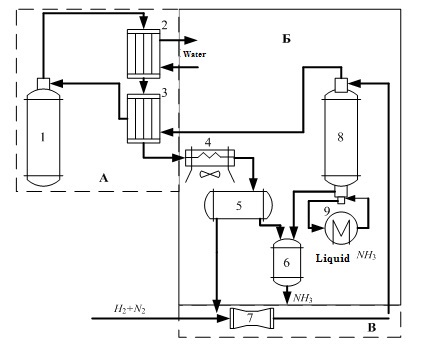
Figure 1.1 – Flow diagram of the ammonia synthesis column.
In Fig. 1.1 the following notation:
- Ammonia synthesis column;
- Water refrigerator;
- Heat exchanger;
- Air cooler;
- Separator;
- Collector refrigerator;
- Circulation compressor;
- Condensation column;
- Evaporator.
The column of synthesis of ammonia are basic and the most complex machines plants synthesis. The correct choice of design, sizing and selection of the mode of operation of the column affects its performance, stability and durability.[5]
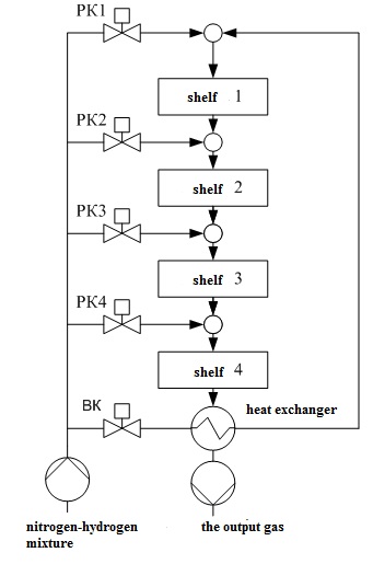
Figure 1.2 – Schematic representation chetyrehbalnoy of the ammonia synthesis column.
In Fig. 1.2 the following notation: 1 – hatch for unloading the catalyst; 2 – Central tube; 3 – the case of the catalyst box; 4 – thermocouple case; 5 – loading hatch; 6 – heat exchanger; 7, 9, 11, 13 – enter the bypass gas; 8, 10, 12, 14 – the catalyst layers; 15 – the case of the column; MT1,..., РК4 valves; VC – inlet valve.
In the catalyst zone of the nitrogen-hydrogen mixture sequentially passes through four layers of catalyst, in which the formation of ammonia. The ammonia synthesis reaction is accompanied by a decrease in volume of the gas mixture and proceeds with the release of large amounts of heat, the maximum temperature in the catalyst layers should be within 390–525 ℃. After the fourth layer of catalyst gas mixture at a temperature 500–515 ℃ rises along the Central tube 2, passes through the tubes of the heat exchanger 6, cools down with up to 325–335 ℃, and emerges from the column. The temperature after the fourth layer of catalyst should not exceed 535 ℃.
The process of ammonia synthesis is a multivariable object of control in the presence of disturbances.[4]
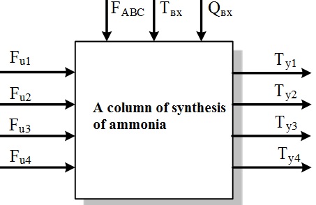
Figure 1.3 &ndash Representation chetyrehbalnoy column of synthesis of ammonia as an object of management
In Fig. 1.3 the following notation: FABC, Qвх, Tвх – flow rate, ammonia concentration and temperature of the input mixture of nitric, respectively; Fu1 – Fu4 – the flow of cold bypass gas; Ty1 – Ty4 – the temperature in the catalyst layers.
Because the chemical reactions in the catalyst layers take place a long time, the object of control can be attributed to the class of objects with transport delay. Therefore, the design of the control system must take this characteristic into account and apply appropriate methods of synthesis of controllers.
Existing control systems have poor quality temperature control in the catalyst layers, which reduces the performance of the ammonia synthesis column due to the lack of compensation of external disturbances on ammonia concentration.
Thus we formulate purpose – increase of yield of the target product due to the modernization of the automatic control system of a column of synthesis of ammonia, which will help stabilize the temperature in each catalyst bed chetyrehpolozyj reactor with non-uniform load.
To achieve this goal it is necessary to solve the following problem:
- Explore the features of the technological process of synthesis of ammonia in the columns.
- To develop a functional system of automatic control of process of synthesis of ammonia in the column. To make the choice of technical means.
- To obtain a mathematical model of the main elements of the automatic control system of ammonia synthesis. To calculate the parameters of the control devices and to conduct the simulation.
2 Development of mathematical model and modeling system
Since the process of synthesis of NH3, like most chemical production processes, is a process that proceeds for a long period of time and is characterized by a smoothly increasing curve with a saturation of the acceleration, we can describe it in the form of aperiodic links of the first order with delay.
The transfer function of the channel management looks like this:[6,7]
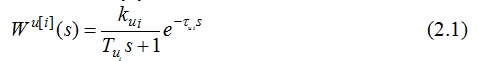
The transfer function of the channel perturbation can be represented as follows:
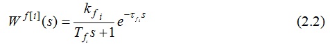
where i = 1..4 is the number of layers of catalyst in which the temperature is measured at the output.
The developed control system of a column of synthesis of ammonia is a set of independent control loops for each layer of the catalyst.
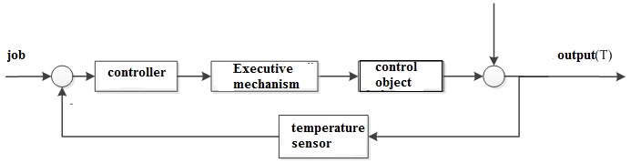
Figure 2.1 – block diagram of temperature control in the i-th layer of the catalyst.[8]
Based on the analysis of the curve of acceleration of the system, it can be concluded that the developed system belongs to the class of systems with transportation
lag. It is known that for such systems a high level of control can be achieved with the use of special structures of PID controllers, containing the so-called
prediction blocks
, also called a Smith predictor. Thus, the decision to use a modification of PPI controller (predictive PI controller), which includes the
controller and the Smith predictor (Fig. 2.2).
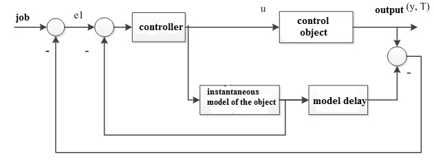
Figure 2.2 – Structure of a control system.
On the basis of the block diagram and the expressions (2.1-2.2) developed the modeling diagram (Fig.2.3).
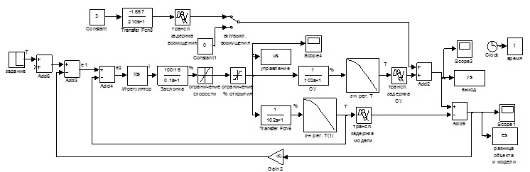
Figure 2.3 – the Scheme of simulation.
In the simulation assumed that the input (nominal) effect is the temperature that must be maintained for the reaction and which is optimal for maximum yield of ammonia −430 ℃. the simulation Results shown in Fig. 2.4.
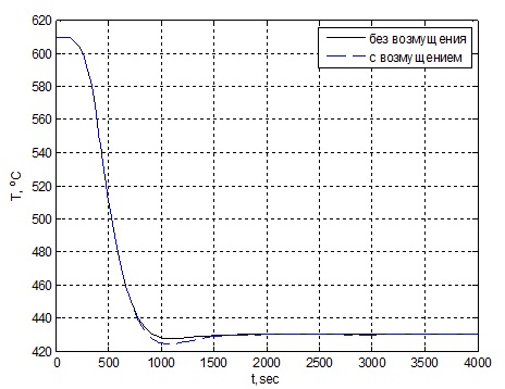
Figure 2.4 – Graph of change of temperature in the first catalyst bed.
Based on the obtained results, we can conclude that the regulator allows to compensate for the perturbation and at the same time the quality indicators of the transition process beyond allowable limits.
3 Technical implementation of the control system
Technical means of ACS in a column of synthesis of ammonia should be located in the premises of the operator and operated in the following conditions:
• minimum ambient temperature – plus 5 ℃;
• the maximum ambient air temperature – plus 40 ℃;
• relative humidity from 40 to 80 %;
• atmospheric pressure of 32 kPa
Allowable temperature in the catalyst layers:
• the temperature in the first catalyst layer – 420–430 ℃;
• the temperature in the second catalyst layer is – 460–465 ℃;
• the temperature in the third catalyst – 480–490 ℃;
• the temperature in the fourth catalyst layer is – 500–530 ℃;
The concentration of ammonia in the input AVS – not less than 3 % (vol.) (this is specified unmanaged option, which can be considered constant and unchanging in time). The concentration of ammonia at the outlet of the column should be not less than 12 %.
To implement the control unit it is advisable to use industrial controllers. Functions that must be performed by the controller and by means of automatic control of process of production of ammonia:
- Collection and primary processing of information.
- The temperature in the catalyst layers;
- Alarm status parameters.
- The procedures of automatic exchange of information between the automation.
Based on these requirements to the automation system of a column of synthesis of ammonia is composed of a functional diagram, the composition of the complex of technical means, shown in Fig. 3.1.
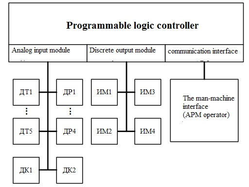
Figure 3.1 – block diagram of the process of producing ammonia.
In Fig. 3.1 legend: T1B,..., DT5 – temperature sensors; DR1,..., DР4 – flow sensors gas mixture; DK1, DK2 sensors of concentration of ammonia; IM1,..., ИМ4 – actuators; AWP – automated working place.
On the basis of GOST 21.404-85 is composed of a functional diagram of the automatic control system of a column of synthesis of ammonia Fig. 3.2.
Animation – Synthesis column
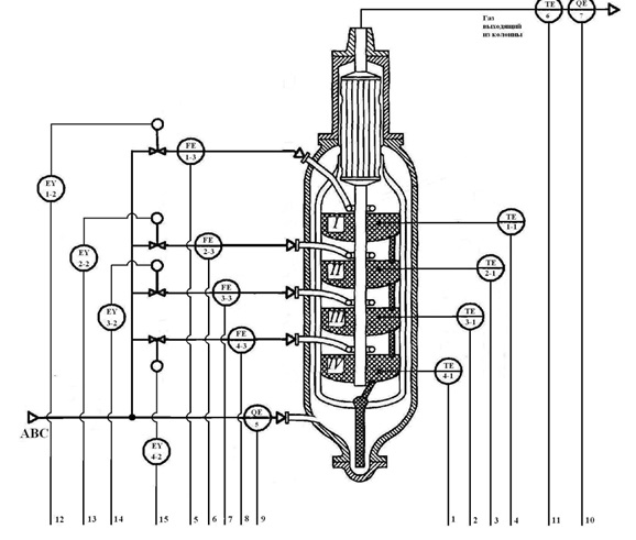
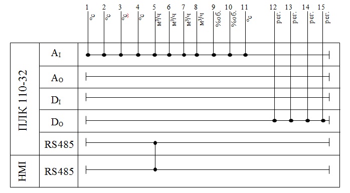
Figure 3.2 – Functional scheme of control system synthesis column.
In the synthesis column on each shelf of a catalyst located temperature sensors (1-1, 2-1, 3-1, 4-1). On each line, the supply cold bypass gas to the synthesis column, is the sensor rashodov (1-3, 2-3, 3-3, 4-3). On the pipeline supplying fresh nitrogen-hydrogen mixture (ABC) is the sensor concentration of ammonia (5). On the pipeline gas emerging from the synthesis column, is located the temperature sensor coming out of the column a mixture of (6) and the sensor of the concentration of ammonia (7). Signals from the temperature sensors, the flow rate of the mixture and the concentration of sensors go to analog inputs of programmable logic controller (PLC). Deviation from the norm is indicated on the screen of the operator's computer Equipment.
With the digital outputs of the PLC on the signals of the Electromechanical converters (1-2, 2-2, 3-2, 4-2), located on each of the actuator (valve) the pipe feeding the cold by-pass gas.
Will produce a variety of complex technical tools:
- Temperature sensors.
As temperature sensors mass flow in the column applicable sensor company ARIES ДТПL015-0110.250 – thermocouple
chromel-Copel
, the material of protective reinforcement – steel 12KH18N10T with a temperature measurement range from −200 to +600 ℃, with isolated work junction, diameter of thermoelectrodes 0.7 mm, with metal switching head, part mounting length 250 mm, in the case 015.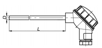
Figure 3.3 – the design of the thermocouple 015.
Because you need to provide the output signal from the temperature sensors in a unified form (signal DC 4...20 mA) applicable Converter ARIES NPT-2.14.1.2 with the conversion range
0…+600 ℃
type and nominal static characteristics ТПL(HC) chromel-drops. - The flow sensors.
As the flow sensors mass flow in the column applicable flow meter Metran-150RFA (flow measurement – differential pressure using an Annubar averaging pressure tubes flowmeter 485). Output signal 4-20 mA corresponds to the current value of the differential pressure or proportional to the flow rate value (the square root of differential pressure).
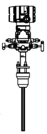
Figure 3.4 – scheme of the external electrical connections and dimensions of the flowmeter Metran-150RFA.
- Sensors concentration.
Choose stationary gas analysis sensor OLCT 100 XP HT high temperature explosion - proof device version, designed to control hazardous gases (including ammonia) at a temperature not exceeding 300 ℃.
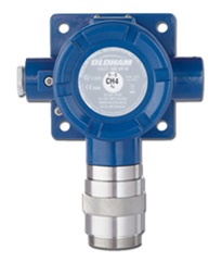
Figure 3.5 – External view of the sensor OLCT 100 XP HT.
- Executive mechanisms.
As the Executive mechanisms governing gas flow in the shelf of the catalyst is applicable flanged electric single turn (maof) actuators for the transmission torque of the actuator valves part-turn principle.
While production and supply is subject to MEOF-100/10-0,25 U-B - mechanism electroisolating single turn flange with a nominal value of torque on the output shaft 100 Nm, with a nominal value of full stroke time 10 s, with a nominal full stroke value of about 0.25., with the current position signaling unit on the output, with current sensor and built-in power supply.
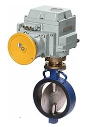
Figure 3.6 – the appearance of maof.
- Industrial controller.
Applicable industrial controller ARIES ПЛК110-220.30.R-M.
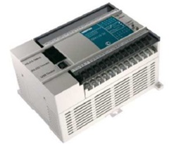
Figure 3.7 – the appearance of the ARIES controller ПЛК110-220.30.R-M.
The controller PLC110 is intended for creation of automated control systems of technological processes in various industries.
A possible variant of the structure of the compounds of the controller when in the automatic control system of technological processes is shown in figure 3.8.
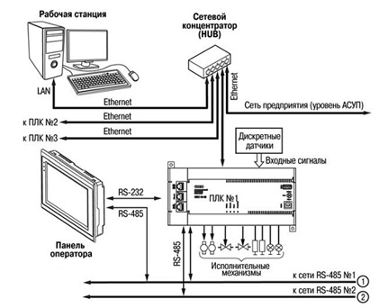
Figure 3.8 – Example of structure of connections when using the PLC in the control system.
Because you must be connected to the controller 11 analog sensors, you must select the analog input module. As such is applicable 2 high-speed input module (8-channel) analog signal input mv110 ARIES-220.8.AC, with supply voltage 220 V AC frequency 47 to 63 Hz.
- The man-machine interface.
For the organization man-machine interface applies the operator panel with touch screen ARIES СП107. It allows you to display the progress of the technological process and edit values for the parameters responsible for the functioning of the system. Has developed communication interfaces.
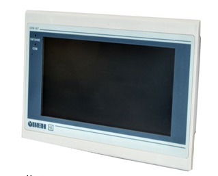
Figure 3.9 – External view and scheme of the external electrical connection panel ARIES СП107.
Conclusion
The technological process of production of ammonia in the columns analysed from the point of view of the control object, the identified input, output, and disturbance variables.
Based on the analysis of existing structures of control systems and control related objects, the selected multi-level decentralized structure of the control system of a column of synthesis of ammonia, in order to ensure the work efficiency, reduce the relative cost of the control system, to improve its reliability and maintainability.
The developed model of the process control system of ammonia synthesis for example, the first shelf chetyrehbalnoy catalyst of the ammonia synthesis column. The resulting simulation transients confirmed by the correspondence between calculated and experimental data and, consequently, the adequacy of the model.
Selection of technical means of ACS in a column of synthesis of ammonia due to the prospect of development of the selected technical means, communication capability with an existing computing equipment, providing the required metrological requirements.
References
- Автоматические приборы, регуляторы и вычислительные системы. Под ред. Б. Д. Кошарского. – Л.: Машинобудування, 1976 – 488 С.
- Бесекерский В. А. Теория систем автоматического регулирования / В. А. Бесекерский, Е. П. Попов – К.: Наука, 1975. – 766 С.
- Дорф Р., Бишоп Р. Современные системы управления: Пер. с англ. Б. И. Копылова. – М.: Лаборатория Базовых Знаний, 2004. – 832 С.
- Клюев А. С. Проектирование систем автоматизации технологических процессов / А. С. Клюев, Б. В. Глазов, А. Х. Дубровский. – М.: Энергия, 1980. – 345 С.
- Сердюк Ю. А. Сетевые технологии как составная часть интегрированных систем управления промышленных предприятий / Ю. А. Сердюк, А. В. Ловейкин // Промышленные измерения, контроль, автоматизация, диагностика. – 2003. – №3-4. – С. 10–13.
- Теоретические основы и технология синтеза аммиака. – под редакцией А. М. Николаева – Киев: Вища школа, 1969 – 256 С.
- Филлипс Ч. Системы управления с обратной связью / Ч. Филлипс, Р. Харбор. – М.: Лаборатория базовых знаний, 2001. – 616 С.
- Штейнберг Ш. Е. Адаптация стандартных регуляторов к условиям эксплуатации в промышленных системах регулирования / Ш. Е. Штейнберг, И. Е. Залуцкий // Промышленные АСУ и контроллеры. – 2003. – №4. – С. 11–14.