
Abstract
Contents
- Introduction
- 1. Relevance of the topic
- 2. The purpose and objectives of the study, the planned results
- 3. Regulation of position
- 3.1 General information
- 3.2 Position regulators
- 3.3 Setpoint position
- 4. Selecting a microcontroller
- List of sources
Introduction
Production at modern enterprises is difficult to imagine without electromechanical systems having regulation by position. They are also called positional. Examples of installations with a positioned electric drive can be various hoisting transport units, some types of robots, manipulators [1]. Most often positioning is performed using servo drives, which can be realized both on the basis of the motor of constant and alternating currents.
1. Relevance of the topic
With the increase in the requirements for the quality of products, the requirements for the accuracy of the implementation of control actions in the positioning systems also increase. Also an important factor is the cost and time of development and adjustment of such systems. Therefore, the question arises in choosing an appropriate microcontroller and the software used to program it.
2. The purpose and objectives of the study, the planned results
The purpose of this work is the development and implementation of a system of subordinate regulation of the position of the electric drive. To solve the problem, you need to choose a microcontroller that has enough power for real-time control system operation, current sensors on the Hall effect, velocity and position sensors. The system will be implemented on the basis of an already existing laboratory stand, which includes two DC motors, a tachogenerator and a position transmitter, two thyristor converters, galvanic isolation and a microprocessor board selected for the implementation of the task.
3. Regulation of position
3.1 General information
To ensure the execution of a number of technological processes, it is required to move the executive bodies of working machines and mechanisms to a given point in space or a plane and to fix them there (fixation) with a specified accuracy [2].
In cases where the positioning accuracy is not high, limit switches are used, which disconnect the drive when approaching them.
If it is necessary to obtain high accuracy of position control and ensure the qualitative nature of the motion of the executive body, a closed-loop electric drive with position feedback is used. In this case, the system automatically generates a signal at the beginning of the braking and provides a given accuracy of the stopping of the actuator (for example, stopping the robotic arm) [3].
The system of subordinate position control is, in fact, augmented by the speed control system, to which one more contour is added. Let's enumerate the contour of the position control system, starting from the external: the position contour, followed by the speed loop, and the innermost – the current loop. Thus, each circuit maintains its value at the required level by means of its regulator. If we want to adjust the position, then the best (or faster) speed we can control is because the speed directly affects the position change (speed is the derivative of the position), and all other quantities (current, voltage and other) affect the position in a more complex manner, more difficult to regulate. Further, if we now want to regulate the speed, then the best thing we can control is the motor torque, since the torque determines the acceleration of the drive, and it is also the simplest mathematical law associated with speed. Since for the motor the moment is proportional to the current (for the DC motor this is true in explicit form, and for AC motors it is valid for the moment-forming component of the current in the vector control), then for torque regulation, it is necessary to control the voltage on the inverter of the converter, because the current and voltage are connected in the first approximation in terms of the simple differential equation [5].
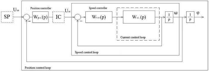
Fig. 1 – A simplified block diagram of the SAR provisions
The SAR system of the position may have a different structure, namely: 1. There is a setpoint position (SP) and a linear position controller (PC); 2. There is no SP, there is an intensity detector (ID) with a linear or parabolic PC; 3. Only with linear or parabolic PC.
3.2 Position regulators
Three meanings are distinguished from the values of intermediate coordinates:
– small movements (Fig. 2a), characterized by a linear mode of operation, i.e. in this case neither acceleration nor speed reaches the limits;
– mean displacements (Fig. 2b), when the regulator enters the saturation, i.e. acceleration reaches the limit level;
– large movements (Fig. 2c), when, during testing, speed and acceleration reach their levels of limitation. [6]
In order to work out small movements, in case of setting all contours, a proportional position controller will be required for the modular optimum. If there is a moment of resistance on the motor shaft, the electric drive will work out a small movement with a static error.
Adjusting to the modular optimum gives a process with overshoot on the position, which for most mechanisms is either not desirable or unacceptable. In addition, the regime of small displacements for most positioning mechanisms is not characteristic. Therefore, such a setting for the development of medium and large displacements can not guarantee either a minimum time, no overshooting, or ensuring a given accuracy.
In order to work out the average movements in a minimum time without overshooting, the ratio of the position controller must change depending on the value of the initial speed, and, consequently, on the set angle. Therefore, if the ratio of the position controller is constant, then only for one value of the initial speed. For other cases – working off or with a slower deceleration at the end, i.e. with tightening and the working time will increase, or there will be a reordering and tightening. To eliminate undesirable overshoot, the regulator's ratio is selected from the condition that the initial speed and the maximum are equal, which corresponds to the largest average displacement. Thus, for a given displacement greater than the largest average, the movement will be worked out as a large trapezoidal schedule without reaching and overshooting [8].
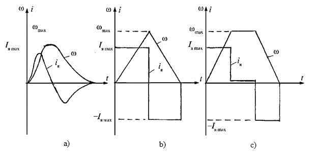
Fig. 2 – The diagram of the change in speed and current of the motor of the position electric drive for small (a), medium (b), and large (in) displacements
In the position control system, the construction of the current and speed loops occurs in the same way as in the SAR speed, and the adjustment of the position controller already depends on the movements with which the system is to be operated. Thus, the position controller is often proportional, and the speed control loop is either proportional or proportional-integral. In the case of a proportional speed controller, if there is a static resistance moment, the specified movement will be worked out with an error. The system with the proportional-integral speed controller is astatic by the disturbing effect.
In systems with a position controller, ID is also used, which, depending on its structure, makes it possible to limit either a jerk, or acceleration, or both acceleration and jerk.
A system with a linear position and ID regulator can provide only the control that is optimal in speed, when working on a trapezoidal tachogram. To work on a triangular tachogram, which ensures optimal working out of large and medium displacements, it is necessary to use a position controller with a non-linear characteristic, the adjustment of which is quite difficult.
There are also systems with a setpoint intensity converter. Such systems can provide the optimal speed control only in the case when the value of the static moment is known, which is unchanged. The disadvantage of this system is the absence of a restriction on acceleration, which in various technological processes may be unacceptable.
Figure 3 shows an idealized rational timetable for the motion of the electric drive during the development of a single movement (step) of the executive body [3].
Fig. 3 – Rational diagram of the motion of the electric drive
The most rational is considered to be a triangular (trapezoidal) tachogram when working out an average (large) displacement.
This allows full use of the overload capability of the engine and eliminates the occurrence of overshoot on the position. For the system under consideration, the following requirements are imposed on the electric drive: limiting the magnitude of acceleration and jerking in the formation of a speed reference and the inadmissibility of overshoot by position [4].
3.3 Setpoint position
Consider the principle of operation of the positioner in the open loop. First, it forms the acceleration reference diagram
![]() in the form of a piecewise-linear approximation of the tabular dependence, the node points of which are calculated based on the amount of movement being processed
in the form of a piecewise-linear approximation of the tabular dependence, the node points of which are calculated based on the amount of movement being processed
![]() and the desired time of his work
and the desired time of his work
![]() taking into account speed limits
taking into account speed limits
![]() and acceleration
and acceleration
![]() of drive (and sometimes jerk
of drive (and sometimes jerk
![]() ) in accordance with the accepted optimization criterion. The resulting signal is integrated twice, resulting in the desired velocity variation diagrams
) in accordance with the accepted optimization criterion. The resulting signal is integrated twice, resulting in the desired velocity variation diagrams
![]() and position
and position
![]() respectively [9].
respectively [9].

a)
b)
Fig. 4 – Structure of the position setpoint generator operating according to the open principle a) – without restriction on the jerk; b) – with restriction on a jerk
To certain position control systems, as noted earlier, high accuracy requirements are imposed, in particular the absence of overshoot. Systems that have SP have low speed. This is due to the presence of three control loops (current, speed, position). To reduce overshoot, it is necessary to reduce the ratio of the position controller, which entails a decrease in the performance.
To increase the speed of use combined control of the control effect. It consists in calculating the coefficients of the correcting links based on the modular optimum condition (see Fig. 5). However, such a structure does not allow to get rid completely of overshoot.
a)
b)
Fig. 5 – The SP structure that implements the combined management of the control action: a) – without restriction on the jerk; b) – with restriction on a jerk
There is a method that allows to parameterize the systems of subordinate regulation using standard polynomials used in the synthesis of modal control. Thus, one can achieve either a very small overshoot, or none at all [10].
4. Selecting a microcontroller
For the realization of the given automation task, sufficient speed is required, as well as work with the ADC.
The task of the board will be both reception and transmission of signals. Depending on the implementation of the system, there will be either 1 or 4 control signals, and the signals received will be armature current, voltage and position sensor signal.
Having evaluated all the necessary parameters, the choice fell on the STM32F4Discovery debug card. This board has on its base microcontroller STM32F407VGT6 (168 MHz, 1 MB Flash, 192 KB of RAM, LQFP100), which has enough power for the correct operation of the control system.
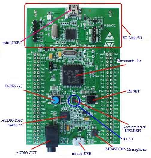
Fig. 6 – The appearance of the board
Another important factor is the ability to program the board via the Matlab/Simulink software package. To implement the task, there is an addition of Waijung , which allows you to conveniently program various microprocessor boards, including the one used in this work.
Main characteristics of this board:
- The 32-bit STM32F407VGT6 microcontroller with the ARM Cortex-M4F core with 1 MB of program memory and 193 Kb of RAM in the 100-pin LQFP100 box with a clock speed 168 MHz. Built-in floating point operations ( FPU )
- Built-in ST-LINK / V2 programmer/debugger with the ability to select the operating mode (allows programming external chips using the SWD connector for programming and debugging)
- Board power: via the USB bus or from an external 5V power supply
- Power for external devices: 3V and 5V
- Eight LEDs: LD1 (red/green) for bus activity indication USB , LD2 (red) for 3.3V power, 4 user diodes: LD3 (orange), LD4 (green), LD5 (red) and LD6 (blue), 2 diodes USB OTG : LD7 (green) for VBus and LD8 (red) when overloading
- Two buttons ( Reset and User )
- USB OTG with connector micro-AB
- Output pads for all microcontroller I/O pins for quick connection to the breadboard and simple measurement
A big plus is the presence in the microcontroller of a module for working with floating-point numbers, which increases the processing speed in applications related, for example, with spectral analysis (for FFT calculation) or in UAVs for orientation algorithms [7].
List of sources
- Босак А.В. Управление позиционным электроприводом с неавтономной задающей моделью и нечеткими регуляторами. Дисс. ... Канд. тех. наук. Киев, 2016. 212 с.
- Электрический привод: Учеб. пособие для сред. проф. образования / Москаленко В.В. – 2-е изд., стед. – М.: Издательский центр
Академия
СПО 2004. – 368 с. - Регулирование положения электроприводов
Режим доступа:Life-Prog
. - Чалый В.В. Синтез систем управления электромеханическими обьектами с применением интеллектуальных модулей на основе оборудования фирмы Control Technique – электронный ресурс. Режим доступа:
Портал магистров ДонНТУ
- Поддержание положения в сервоприводе: подчинённое регулирование vs шаговый режим – электронный ресурс. Режим доступа:
GeekTimes
- САР положения электропривода – электронный ресурс. Режим доступа:
Exponenta
- Оценочная плата STM32F4 Discovery с STM32F407 – электронный ресурс. Режим доступа:
Роботоша
- Машиностроение. Энциклопедия / ред. совет: К.В. Фролов (пред.) и др. М38 М.: Машиностроение. Электроприводы. Т. IV-2 / Л.Б. Масандилов, Ю.Н. Сергиевский, С.К. Козырев и др.; под общ. ред. Л.Б. Масандилова, 2012. 520 с.: ил.
- Толочко О.И., Коцегуб П.Х., Розкаряка П. И. Особенности цифровой реализации оптимальных алгоритмов управления позиционным электроприводом // Вісник КДПУ. Випуск 3/2006 (39). Частина 1". – Кременчук: КДПУ. – 2004. – С. 8-11.
- Розкаряка, П.И. Разработка оптимальных по тепловым потерям систем управления позиционным электроприводом : дис. ... канд. техн. наук : 05.09.03: защищена 07.10.10 / П. И. Розкаряка. – Донецк, 2010. – 230с.