
Abstract on the theme of master's work
Content
- Introduction
- 1. Theme urgency
- 2. Purpose and objectives of the study
- 3. Overview of motor loading systems
- 3.1. Load device according to the generator-motor system (GD)
- 3.2. Mechanical loading (disc or shoe brake)
- 3.3. DC motor in dynamic braking mode
- 3.4. Controlled loading machine using DC motor
- 3.5. Controlled loading machine using AC motor
- 4. Load control system
- 5. Motor load
- 5.1 Active moment
- 5.2 Reactive moment
- 5.3 Quadratic moment
- 6. Selecting the microcontroller
- 7. Choice of current sensors
- conclusions
- List of sources
Introduction
Modern production is difficult to imagine without an electric drive, since it is used practically at all stages of production. Such a wide application of the electric drive was due to its versatility and ease of use. During the operation of the electric motor, the resistance moments act on it, which indicates its useful operation, since the absence of the moment of resistance indicates that the drive is idling, and in this mode the drive does not perform useful work and simply consumes electricity from the power supply. The load acting on the engine can be active or reactive, can operate with a constant value or vary during the engine operation, and can also operate continuously, or be superimposed and discontinued abruptly.
1. Theme urgency
Since the electric actuator will have various moments of resistance during its operation, the designer is faced with the task of choosing the motor's power, the size of which would overcome the load, and the engine did not consume too much electricity. After all, the choice of an electric motor with too much reserve at the moment will lead to unjustified energy costs. This feature should be taken into account when designing all motors and systems. For the correct choice of the electric motor, the designer conducts the engine research not only during idling, but also during its loading, so special systems are needed to reconstruct the real load in the laboratory, which indicates the relevance and importance of such systems.
2. Purpose and objectives of the study
The purpose of this work is the development and implementation of the electric drive loading system, which will create a load as close as possible to the real one.
The created system must satisfy the following requirements:
- Ability to control the amount of load during engine operation;
- The possibility of creating a load, the magnitude of which will vary according to different laws;
- The ability to record the graphs of the physical quantities of the engine and the load machine.
As a controller, modern microprocessor technology will be used in the form of the stm32f4 discovery debug card.
To solve the problem, it is necessary to connect current sensors to the Hall effect, and also to connect and program the board to control the system in real time.
3. Overview of motor loading systems
Loading systems have been used for a long time and are used to this day. The loading systems include:
- Load device according to the generator-motor system (GD);
- Mechanical loading (disc or shoe brake);
- DC motor in dynamic braking mode;
- Controlled loading machine with the using DC motor;
- Controlled loading machine with the using јC motor.
3.1. Load device according to the generator-motor system (GD)
This system was very popular before, because it allows you to control the value of the moment of resistance with sufficient accuracy. Such a system is used in laboratory 8.101 for laboratory work to this day. A schematic diagram of the load device is shown in Figure 3.1 [9].
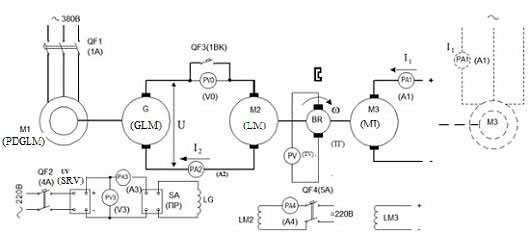
Figure 3.1 – Schematic diagram of the load device
This system allows you to obtain data to build the necessary characteristics of the test and loading machine.
The structure of such a system includes:
- The investigated machine (MI);
- Loading machine (LM);
- The generator of the loading machine (GLM);
- Drive motor load machine (PDGLM);
- Source of regulated voltage (SRV).
As MI, LM and GLM, DC motor is used with independent excitation, for PDGLM, a short-circuited rotor is used.
The IM shaft (M3) is mechanically connected to the shaft of the load machine (M2), which is powered by the GLM with the drive motor (M1).
To conduct research, it is necessary first of all to wind the anchor and excite the MI, winding the HM excitation, and also connect the stator PDGLM to power supplies. In this case, the MI will operate in idle mode, since HM will not create a moment of resistance. To MI worked in the motor mode, it is necessary to create a moment of resistance. To do this, it is necessary to connect the excitation winding of the GLM to the SRV, after which the GLM will go into the generator mode, and will feed the LM. With the help of the NIR, the magnitude of the excitation current of the GLM changes, which leads to a change in the supply voltage of the LM, which affects the magnitude of the IM resistance moment.
Such a system makes it possible to investigate MI in all operating modes, even in the generator mode, it is sufficient to change the polarity of the excitation current of the GLM.
The advantages of this system include:
- The ability to control the magnitude of the moment of resistance;
- A simple principle of work;
- Quite precise regulation;
- The possibility of an abrupt application of the load during operation;
- The possibility of forming an active moment of resistance.
The shortcomings of the system include:
- Complexity of design and large dimensions (a large number of engines);
- There is no possibility to set a change in the moment of resistance by any law.
Despite its merits, such a system finds limited application, since it does not allow to fully study the work of EP.
3.2. Mechanical loading (disc or shoe brake)
The simplest way of loading the engine is by using a mechanical brake that is directly connected to the motor shaft and with its pads (or discs) compresses the shaft and thereby creates a moment of resistance of the engine under investigation.
Advantages of such a system are:
- Simplicity of construction and small dimensions;
- A simple principle of operation and management;
- Low cost.
But because of their significant shortcomings, the use of such a system is very limited, in particular:
- There is no possibility of an abrupt application of the load during operation;
- Small range of load regulation;
- The absence of the possibility of specifying a load by any law;
- The absence of the possibility of forming an active moment of resistance.
Given these shortcomings, it is not desirable to make such a loading system.
In addition to disc brakes and lock brakes, electromagnetic couplings of dry or viscous friction and slip clutches as well as powder couplings can be used as the loading system. Such devices have their own peculiarities (low efficiency at low speeds, small transmitted torque, low reliability with sudden load changes and considerable inertia), but they have the same drawbacks as disk and block, so it is undesirable to use such devices for the loading system [6].
3.3 DC motor in dynamic braking mode
Another way to create a load on the shaft of the machine under investigation is to use an additional DC excitation as a loader, which operates in the dynamic braking mode.
The connection diagram of the loader is shown in Figure 3.2. [10].
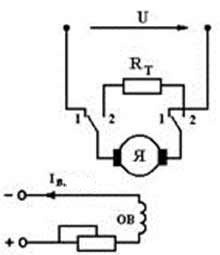
Figure 3.2 – Wiring diagram of the load machine in D¬ mode
The essence of this method is that the anchor chain of the loader is closed to the braking resistor, which leads to the appearance of a negative current in the anchor circuit (transition to the braking mode), which creates a moment of resistance for the machine under investigation. The magnitude of the moment of resistance is controlled by changing the excitation current of the LM, increasing the excitation current increases the resistance moment and, conversely, vice versa – a decrease in the excitation current leads to a decrease in the moment of resistance.
The advantages of such a system include:
- The ability to control the value of the moment of resistance with sufficient accuracy;
- The possibility of supplying the load is almost abrupt;
- Simple design and operating principle;
- Ability to connect the load during operation;
- The ability to set the change of the resistance moment according to the established law.
But this system has significant drawbacks:
- The loader can operate for a short time. This drawback is due to the fact that during the dynamic braking in the anchor chain a large current flows, which leads to overheating of the engine and the engine may fail;
- Inefficiency. This feature of the system is due to the fact that the brake energy is dissipated on the braking resistor in the form of heat.
Due to the fact that such a loader can not be used for a long period of time, it is not practical to apply such a system, since during the research it is necessary to observe the operation of the engine for a long time and repeatedly change the resistance moment for a better analysis.
3.4. Controlled loading machine with the using DC motor
In recent decades, there has been a tendency to use automated electric drives as systems that simulate the real load [11].
With the development of microprocessor technology, it became possible to build more complex and multifunctional control systems for the electric drive. An example of such a system is a loading machine based on the DC motor and a thyristor converter (TP).
This system has in its composition: a reversible thyristor converter, a DC motor with independent excitation and an automatic control system (ACS) with a closed loop of the armature current.
The essence of such a system is that the value of the moment and the law of its change are programmed programmatically, which is fed to the closed loop of current regulation and by means of the TP a task is set up for the motor.
Such a system has obvious advantages over other systems:
- Accurate control of the moment of resistance;
- The possibility of programmatically specifying a moment that varies according to a certain law;
- The possibility of forming an active and reactive moment of resistance, thanks to a reversible TP;
- You can connect the load during operation;
- Relatively small size.
The drawback of such a system is only the use of DC motor, since this engine has a collector in its composition, which is a weak link in the DC motor.
Thanks to its advantages, this system will be used in master's work.
3.5. Controlled loading machine using AC motor
The most modern loading system of all presented. This system has the same advantages as the system with DC motor, but it has a more complex control system. Since the system uses AC motor, it is necessary to use a frequency converter with vector control, which has a higher price than a thyristor converter for DC motor.
Such a system, as well as the DC motor system, allows to fully control the magnitude of the moment of resistance and the law of its change, but because of its high price and the need to use the recovery module, its use is inexpedient.
In control systems of the load machine with controlled AC and DC motor, which are rigidly connected to the shaft of the examined machine, it is possible to simulate a two-mass electromechanical system (and even multi-mass), which is a serious argument in their favor.
4. Load control system
To control the load machine, a closed loop system with current feedback will be used.
A certain complexity of using such a system is the adjustment of the regulator. The system must fulfill the task with the required speed and accuracy.
The structural diagram of such a system is shown in Figure 4.1.
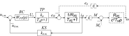
Figure 4.1 – Structural diagram of the current control loop
The following notations are used in this scheme:
- WPT(p) – is the current controller;
- kμ – is the gain of the TP;
- Tμ – is the time constant of TP;
- eP – is the voltage at the output of the TP;
- Uy – control voltage at the current controller output;
- uз.m.– a signal to set the motor current;
- uo.m.– voltage at the output of the current sensor;
- e∂ – couter-EMF of the motor;
- Rя∑ – resistance of the anchor;
- Tя∑ – is the time constant of the anchor chain;
- k∂.m. – is the gain of the current sensor;
- iI – armature current;
- c – design constant of the motor;
- M and M c – are the motor torque and the moment of resistance;
- TM – is the time constant of the mechanical link;
- ω – speed of rotation of the engine.
In this system, a PI current controller will be used, which, if properly tuned, can provide the optimal system speed and accuracy.
The transfer function of the current controller is as follows:
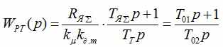
Since the current loop will be tuned according to a modular optimum, the time constant of the regulator TT is:

Due to this setting, the current loop will meet all the requirements for the control system, in particular:
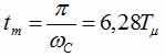
Time to reach the maximum:
The time of the first attaiLMent of the steady state value:

Deregulation:

In Figure 4.2, the closed loop transition characteristic displays all the quality indicators.
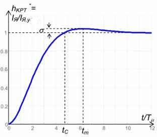
Figure 4.2 – Transient response of a closed loop
Introduction to the control system of the electric drive of a separate current regulator allows to solve the following tasks:
- By the inertia compensation in a power circuit due to the action of the current controller form a curve of the armature current iя = f(t) so as to provide, perhaps more rapid growth in the absence of current overshoot;
- Effectively limit the maximum current values during overloads, because the current loop is the fastest;
- Effectively limit the fluctuations in current and speed with fluctuations in the voltage of the supply network [7].
5. Motor load
The task of my work is the realization of the load system of the electric drive, which will provide the possibility of creating the closest possible to the reality moment of resistance. These moments include the active and reactive moment, as well as the quadratic load.
5.1. Active moment
Active forces and moments are those that are created by external sources of mechanical energy external to the engine and do not depend on the motion of the electric drive (speed and direction). Such forces and moments occur during the lifting and descent of loads, wind load on the mechanisms of rotation and movement, etc. [8].
Figure 5.1 simplifies the kinematic scheme of the load-lifting mechanism and its mechanical characteristic.
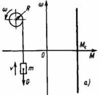
Figure 5.1 – Active resistance moment
The magnitude of the moment of gravity of the load G is equal to:
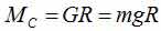
Gravity, both during lifting and during descent, is directed to one side of the descent and is unchanged in magnitude. Accordingly, the mechanical characteristic of the actuator ω = f(M C) in this case has the form of the line MC.act = const [8].
5.2 Reactive moment
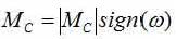
Reactive forces and moments are called forces and moments of resistance to movement, arising as a reaction to the active driving moment developed by the engine, or any other active driving moment, for example, due to gravity or inertia. The reactive moment of the resistance is the moment, which is always directed in the opposite direction to the direction of rotation of the motor [8].
Loads of dry, viscous and valve friction are referred to such load moments. In Figure 5.2, the mechanical characteristic of the electric drive under the action of the moment of resistance, such as dry friction.
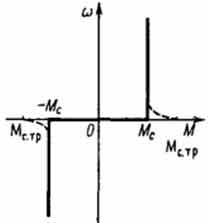
Figure 5.2 – Reactive moment of resistance
The moments of dry friction are unchanged in magnitude, but change their sign in accordance with the direction of rotation of the motor shaft.
The moment of resistance in this case is:
5.3 Quadratic moment
The quadratic moment of resistance is a torque whose magnitude varies in proportion to the square of the motor's rotation speed, so even a slight increase in the speed of the drive leads to a significant increase in the load on the motor. Such a load during operation is tested by pumps, fans and compressors.
The moment of resistance in general form is:
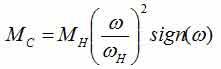
where: MH – rated motor torque; ωH – nominal speed of rotation of the engine; ω – current speed of rotation of the engine.
6. Selecting the microcontroller
To realize the automation task, the STM32f4 discovery board was chosen, which will provide the required speed, and, thanks to the ADC, will allow the analog signals of the armature currents of the investigated and loading machine to be digitized.
During operation, the board will generate two control signals, as well as digitize the signals of the current sensors and the speed sensor of the examined machine with the possibility of their further observation.
The STM32F4 Discovery board (Figure 6.1) is designed to familiarize with the capabilities of the 32-bit MK based on the ARM architecture, as well as to implement its own devices and applications using the board hardware [1].
The appearance of this board is shown in Figure 6.1 [2].
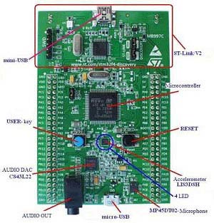
Figure 6.1 – The appearance of the board STM32F4
The STM32F4 Discovery card is equipped with:
- The STM32F407VGT6 microcontroller with a 168MHz Cortex-M4F core, 1 MB of Flash memory, 192 KB of RAM in the LQFP100 package;
- The ST-Link/V2 debugger for debugging and programming the MK;
- The board is powered via USB or from an external 5 V power supply;
- Output pads of all I/O pins of the microcontroller for quick and easy connection to the prototyping board.
Thus, the debugger board is equipped with a large number of peripherals, which will enable it to implement a loading system on it [1].
Due to its layout design, the stm board will allow you to connect all the necessary signals without using soldering. This board was chosen because it can be programmed with the Matlab/Simulink software package, and also provides sufficient speed. For programming, the Waijung library is used, which makes it possible to implement the task.
7. Choice of current sensors
As current sensors, Allegro Hall current sensors have been selected to measure the motor currents with high accuracy. Its appearance is shown in Figure 7.1.
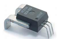
Figure 7.1 – Current sensor from ALLEGRO ACS750 series
The advantages of this type of sensors include:
- High insulation voltage 2500 V;
- Low internal resistance 120 mΩ;
- The measurement error is less than 1%;
- Sensors for 50, 75 and 100 A;
- The extended temperature range is -40 ... + 150o C;
- The sensor has an integrated power bus;
- The voltage at the output of the sensor is proportional to the current at its input;
- The ability to measure DC and AC;
- The presence of galvanic isolation [3].
- IP+ and IP- – terminals for current measurement;
- VCC – sensor power supply;
- GND – is the signal ground;
- VIOUT – is the analog output of the sensor.
- The sensor is connected to the motor armature winding for current measurement and is connected to the STM board for fixing the measurements. The connection diagram of the sensor is shown in Figure 7.3.
- Since during the operation of the DC motor in its windings both positive and negative currents will be formed, it is necessary to use an ac sensor.
- In order to be able to fix the measured value, the sensor output is connected to the ADC of the STM board, so a fixed value will be represented as a set of numbers. Since the ADC is 12-bit, then to calculate the voltage after digitization, use the formula:
- To convert the voltage to current, you must use the formula:
- Since the sensor of this type is sensitive to external influences, the measured value can have large noises, so to improve the measurement it is desirable to use the RC filter (Fig. 7.2).
- Ѕугаев ¬.». Ћабораторный практикум дл€ изучени€ микроконтроллеров архитектуры ARM Cortex-M4 на базе отладочного модул€ STM32F4 Discovery / ¬.». Ѕугаев, ћ.ѕ. ћусиенко, я.ћ. райнык Ц ћосква-Ќиколаев: ћ‘“»-„√”, 2013. Ц 71 с
- 32-разр€дные микроконтроллеры STM и 8-и разр€дные AVR, - электронный ресурс. –ежим доступа: http://webstm32.sytes.net
- ƒатчики тока ACS750 фирмы Allegro: теори€ и практика / јлександр ”ткин. - „ел€бинск, - электронный ресурс. –ежим доступа: https://www.soel.ru
- Thermally Enhanced, Fully Integrated, Hall Effect-Based Linear Current Sensor IC with 100 Current Conductor, - электронный ресурс. –ежим доступа: http://files.amperka.ru
- –абота с датчиками тока на эффекте ’олла: ACS758, - электронный ресурс. –ежим доступа: https://geektimes.ru
- Ёлектромагнитные муфты, - электронный ресурс. –ежим доступа: http://electricalschool.info
- —истемы управлени€ электроприводами. ”чебное пособие дл€ студентов высших учебных заведений, - электронный ресурс. –ежим доступа: http://arigato.do.am
- лючев ¬.». “еори€ Ёлектропривода / ¬.». лючев. - »здательство Ёнергоатомиздат, 2001.-288 с.
- „епак A.A. ћетодические указани€ к лабораторным работам по теории электропривода, часть перва€ / —ост.: ј. ј. „епак, ¬.‘.Ѕорисенко. - ƒонецк: ƒќЌЌ“”, 2016., 62 с.
- “орможение ƒѕ“. ћеханические характеристики ƒѕ“ в тормозных режимах, - электронный ресурс. –ежим доступа: http://poznayka.org
- Ѕуров ј. Ќ. Ёкспериментальный стенд дл€ исследовани€ электрооборудовани€ ветроэнергетических установок: структура и аппаратна€ реализаци€ / ј. Ќ. Ѕуров - ¬естник рЌ” имени ћихаила ќстроградского. - ременчуг, рЌ” - 2015, ¬ыпуск 2, с. 43-39
Due to the galvanic isolation, the sensor output signal can be directly connected to the microcontroller ADC for further processing.
Figure 7.2 shows the sensor wiring diagram [4].
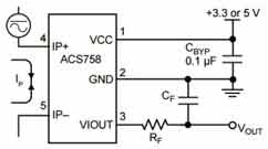
Figure 7.2 – Wiring diagram of the current sensor
The description of the sensor inputs and outputs is as follows:
The principle of the sensor operation is as follows: when the current 1A flows through the sensor leads 4-5, the voltage at the sensor output VIOUT is increased by the value indicated in the sensor parameters.
The principle of operation with the sensor is as follows:
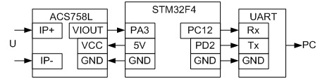
Figure 7.3 – Wiring diagram of the current sensor
To measure AC, the sensor has a so called reference point
. This reference point is 1/2 power supply (VCC). With a positive value of the measured current, a signal equal to 1/2VCC + I·0.02V
will be formed at the output of the sensor , and for a negative value – 1/2VCC - I·0.02V
. The output of the sensor forms a sinusoid, where zero
is 1/2VCC [5].
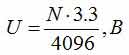
where: N – code at the output of the ADC; 4096 – is the maximum output code.
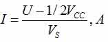
where: U – voltage at the sensor output, V; 1/2VCC – zero point of measurement, V; VS – change the sensor output voltage by 1A load, V.
Conclusions
In this lecture, the main load-bearing systems of the electric motor were considered. Their advantages and disadvantages are revealed. Among the systems considered, preference was given to a controlled loading machine using DC motor, since this system meets the requirements. The controller will use the debug board stm32f4 discovery, and as sensors – current sensors on the Hall effect of Allegro.
Further research will be aimed at implementing this system, with the goal of creating a laboratory bench for studying the engine under load conditions.