DonNTU master Bai Dmitriy

Most of the extracted minerals can not be used in their original form for direct production. This is due to the fact that the final technological processes of processing of minerals become technically and economically viable only if it contains a certain minimum of the extracted component.
The processing operations to which the ore is subjected at the enrichment plant are divided into: basic (actually concentrating); preparatory and auxiliary. All existing methods of enrichment are based on differences in the physical or physico–chemical properties of individual components of the mineral. Processing of minerals in concentrating plants includes a number of successive operations, as a result of which separation of useful components from impurities is achieved. According to their purpose, the processing of minerals is divided into preparatory, basic and auxiliary.
Crushing is carried out at special crushing plants. Crushing is the process of the destruction of solids with a reduction in the size of pieces to a given size, by the action of external forces that overcome internal bonding forces, which bind together particles of solid matter.[1]
Pressing is a type of pressure treatment in which a metal is squeezed out of a closed cavity through an opening in the matrix corresponding to the section of the profile being compressed. This is a modern way of obtaining various profile blanks.
The coal seams developed at the present time are characterized by high ash content from 35% or more. The use of such coals in metallurgy and power engineering requires additional costs. The crushing in most cases is the main and often the most energy–intensive operation designed to break down to the required size of raw materials, as well as to uncover mutually intergrown aggregates and to form particles of individual materials.
Currently, coal is enriched in concentrators that use technically possible equipment. Analysis and identification of the most important technological parameters for more economical pressing and crushing of coal at its various stages is very actual.
The purpose of this work is to study and analyze existing and new types of crushers and presses, identify the most important technological parameters for concentrating mills. To achieve this goal, you must complete the tasks:
1) To consider and analyze the efficiency of the application of currently available crushers in concentrating plants;
2) Determine the features of the technology of crushing;
3) Determine the features of the technology of pressing;
Crushing is based on the action of external forces–compression, stretching, bending or shearing, which are manifested to the greatest extent in weakened sections of the piece caused by defects in its structure, stratification, porosity and fracturing. For the processes of crushing, the most important characteristics are the strength and crushing of the pieces.
Crushing is carried out by the working organ of crushing machines, are compression, impact, abrasion and splitting. In some cases, these methods are combined together, for example, a combination of the actions of bending forces and tearing.
The choice of the method of crushing is based on the properties of materials (brittleness, hardness, propensity to grind), the size of the pieces of material and the required degree of grinding. Solid materials are most effectively crushed by impact and crushing, plastic – crushing in combination with abrasion, brittle materials – splitting.
The degree of quality of the final product depends on the correct choice of the crushing method and the crushing machine. The crushing is to be carried out in series with the stages on several corresponding sized crushers. Virtually never completely breaks all the material in one machine. At the moment, crushers of various designs are successfully being explored. Requirements for which any crusher should be doubled are presented below:
1) Crushing is a very energy–intensive process, the specific consumption is reduced to a minimum. Remember, as the degree of grinding increases, the productivity of the machine decreases and the energy consumption increases.
2) The dimensions and design of the filling opening must correspond to the strength of the crushing material and the dimensions of the individual pieces. This reduces the downtime of equipment that occurs when the pieces are stuck in the receiving hole.
3) The crushed material must be unloaded quickly and continuously to avoid its re–grinding.
4) The crusher should have some margin (~ 20%) of productivity, if the amount of incoming material is increased, there was no overload.
5) The design of the crusher must mean the rapid replacement of worn or broken parts, so that there is no downtime.
6) The structure of the crusher should include light and inexpensive spare parts. When crushing is often deformed and broken parts when hit non–crushing materials, such parts protect against breakage of expensive parts of crushers from breakage.
7) The crushed material should be as much as possible of the same size and cubed shape.
8) In the process of crushing, a lot of dust and stone fines are formed. They fill the space between the large pieces and so soften the impact, thereby reducing the efficiency of crushing. For this reason, it is necessary to minimize this.
9) The design of the crusher should allow for rapid repair and maintenance of the machine.
The crusher must be cheap, easy to manufacture and operate, easy to maintain, efficient and consume the minimum amount of energy required.[2]
3.1 Jaw сrushers
Jaw crushers are used for large and medium crushing of various materials in many branches of the national economy. They are capable of destroying non-metallic materials of almost all varieties. The main parameter of jaw crushers is the size of the receiving aperture of the crushing chamber formed by the movable and fixed cheeks. Classification of jaw crushers is carried out by the nature of motion of the movable cheek, which is the main working organ of the crusher. This determines the most important technical and operational parameters of the crushers. There are crushers with a simple and with a complex movement of the cheek.
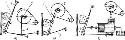
Figure 1. Kinematic schemes of jaw crushers
In crushers with a simple movement of the cheek (SCHD) 1 (Fig. 1, a), the last one is suspended on axis 2. The jaw oscillates along the arc of the circle, which is communicated to it by a rotating eccentric shaft 3, through the connecting rod 4 and spacer plates 5. The material is crushed when the cheeks come together, and when they are removed from each other, the pieces of material fall down and, if they are smaller than the width of the exit slit, drop out of the chamber. Then the cycle repeats. In the JPL, the material is crushed by crushing and, in part, by kinking and splitting, as crushing plates with corrugations in the longitudinal direction are mounted on both cheeks. In crushers with a complex motion of the cheek (SHDS), the lever mechanism has a simpler scheme (Fig. 1, b). The eccentric shaft 3 is directly connected to the connecting rod, which is the movable cheek 1 of the crusher. The lower end of the cheek hinges on the spacer plate 5. The cheek makes a complex motion, along a trajectory reminiscent of an ellipse. As a consequence, in the ZHC material is crushed both by crushing and abrasion, which facilitates the process of crushing of viscous materials. The kinematic scheme of the SCP makes it possible to create relatively larger loads on the material to be crushed than in the SHDS, with identical rotational moments on the drive shafts. This is especially important when crushing large pieces of strong materials. A significant drawback of the DZHP (Fig. 1, a) is the small compression stroke in the upper part of the crushing chamber. For ZHDD, considerable wear of the crushing plates is characteristic. However, the construction of the ZHCS is generally more simple and less metal-consuming.
Depending on the design of the mechanism that drives the cheek, crushers with lever and cam mechanisms are distinguished, as well as with a hydraulic transmission mechanism (Fig. 1, c).
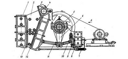
Figure 2. Construction of a jaw crusher with a simple movement of the cheek
A typical design of a jaw crusher for large crushing with a simple movement of the cheek is shown in Fig. 2. The movable cheek 3, whose axis 4 is installed in the sliding bearings fixed to the side walls of the frame 7, receives oscillatory movements through the spacer plates 10 and 11 from the connecting rod 6 suspended on the eccentric part of the shaft 5 driven by the electric motor through a V-belt drive. The working surfaces of the cheeks are lined with replaceable crushing plates 12 and 13. The side walls of the crushing chamber are also lined with interchangeable plates 2. The working surface of the crushing plate is usually made of corrugated and, less often, smooth. The conditions for the capture of pieces and the granulometric composition of the material depend on the longitudinal profile of the plates. The cyclic nature of the operation of jaw crushers creates an uneven load on the motor. To balance the load on the drive shaft, install a flywheel and a flywheel. During operation, it becomes necessary to adjust the width of the output gap of the crushing chamber. In large crushers, for this purpose, a different thickness of the spacer between the abutment 9 and the rear wall of the frame is established. Guaranteed closure of the links of the moving cheek drive mechanism is carried out by a spring 7 and a pull rod 8.
Figure 3. The principle of the jaw crusher
(animation: 3 frames, 15 repetition cycles, 29 kilobytes)
The cyclic nature of the operation of jaw crushers creates an uneven load on the motor. To balance the load on the drive shaft, install a flywheel and a flywheel. During operation, it becomes necessary to adjust the width of the output gap of the crushing chamber. In large crushers, for this purpose, a different thickness of the spacer between the abutment 9 and the rear wall of the frame is established. Guaranteed closure of the links of the moving cheek drive mechanism is carried out by a spring 7 and a pull rod 8. In crushers with a complex motion of the movable cheek, a significant vertical displacement of the cheeks, which causes their abrasive action on pieces of material, leads to increased wear of the crushing plates. Therefore, crushers with complex motion are used mainly for low-abrasive materials. Advantages: their simplicity of design, compactness and a small mass.
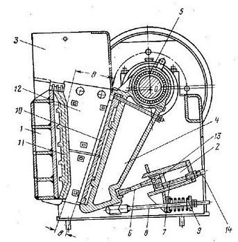
Figure 4. Jaw crusher with complex cheek movement
Figure 4 shows the scheme of a jaw crusher with a complex movement of the cheek of the SCD. The mill is welded. Its side walls are made of steel sheets and are interconnected by the front wall 1 of the box section and the rear beam 2, which is the simultaneous body of the adjusting device 7. A protective cover 3 is attached above the receiving hole.
The movable cheek 4 is fixed to the eccentric portion of the drive shaft 5, a groove is provided at the bottom of the cheek where the insert for the spacer plate 6 is inserted. At the other end, the spacer plate abuts the insert of the adjustment device consisting of a slide 13 and two screws 14. The closing device consists of the thrust 8 and the coil spring 9. The movable cheek has in the lower part an oblique projection on which a crushing lining plate 10 is mounted. The stationary crushing plate 11 rests on the bottom of the projection of the front wall of the frame 1, and from the side walls The dagger is clamped by lining plates 12. [3]
3.2 Cone crushers
Cone crushers favorably differ from jaws in that the process of rock crushing in them is carried out continuously, i.e. there is no idling. Pieces of rock are crushed in the space between two conical surfaces formed by a moving organ and a fixed cone–shaped bowl.[4]
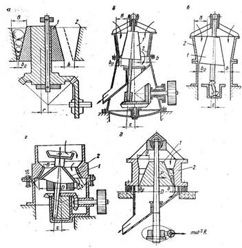
Figure 5. Cone crusher schemes
А – with a fixed axis, б – with a hanging shaft (GKD gyratory), в – with a shaft having a support (MDC), г – with a cantilever shaft supported by a ball bearing (KSD and KMD), д – inertia crusher CID). Workspaces of cone crushers for large, medium and fine crushing differ in configuration. In crushers for large crushing, the cone is steep (the angle at the apex is about 20 °), and in crushers for medium and fine crushing it is flat (the angle at the apex is about 100 °). Cone crushers for large crushing differ from the crushers for small and medium crushing by the amount of eccentricity of the glass, which determines the amplitude of the rocking of the crushing cone. In crushers for large crushing, the eccentricity of the glass is no more than 25 mm, and in crushers for medium and fine crushing, more than 100 mm. [5]
3.3 Roller сrushers
Roll crushers are used for medium and fine crushing of hard rocks. The material is fed to the crusher through the hopper, captured by rolls rotating at the same speed towards each other, crushing and discharging down under the crusher.
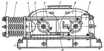
Figure 6. Double Roller Crusher
A machine with smooth or corrugated rolls (Figure 5) consists of a frame 1 of a frame structure. The roller 8 is mounted on bearings housed in split housings 9. The bearing housings 5 of another roller are mounted in the guides 4 and can be moved along them along the bed. The width of the outlet slot is regulated by means of a set of gaskets 10 which are installed between the bodies of fixed and movable bearings. The movable roller is pressed against the stationary system of the upper 6 and lower links with the spring pack 3. The prestressing of the springs, created by the nuts 2, provides the total force on the roller, which ensures the crushing of the material.
When the non–crushing objects enter the machine, the springs are compressed, the rolls diverge and pass them. To prevent dusting, the crushing rolls are closed by a casing with a receiving funnel 7. On crushers with smooth rolls operating in an open cycle, the degree of crushing is 3 to 4, and on crushers with toothed rolls – from 4 to 6.
3.4 Hammer сrushers
Impact crushers are used for crushing soft and medium strength non–abrasive materials.
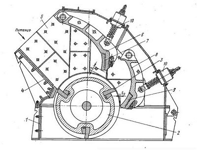
Figure 7. DRC crusher
1 – frame, 2 – rotor, 3 – bila, 4 – upper part of the case for loading the source material, 5 – lining of the shell, 6 and 8 – respectively upper and lower reflective plates, 7 and 9 – lining plates, 10 – clearance of reflective plates.[6]
The main methods of forming products from metal powders are the press, the working organs of which are pressed in molds, which provides the desired shape without mechanical treatment. At present, the press of various designs is successfully used. The quality of the finished product largely depends on the correct choice of the type of press. The main characteristic of the press is its nominal pressure on the workpiece. This parameter is measured in tonsils (often for simplicity is denoted as T) or in kylon– cubes (kN). For a quick recalculation between the quantities, one can use the formula 10kH = 1T. Although most press parameters have intuitively clear "geometric" names, there are a couple of exceptions, which should be mentioned. "Closed Height" is the distance from the tabletop to the press slider in its lower position at the highest stroke (closed height determines the maximum height of the stamp). "Throat depth" is the distance between the slider axis and the edge of the frame, this parameter determines how deep the part can be fed into the working area.
4.1 Screw presses
The formation of briquettes in such presses is due to the movement of sawdust by a screw, pressing and heating. The working principle of a screw briquetting press can be briefly described as follows. Dry sawdust in the bunker is mixed with a tedder and falls on the feed screw, located under the bunker. The filing of sawdust is controlled by changing the speed of the screw. In the press, the auger is compacted and compacted sawdust that is pressed through filters inside the extruder and simultaneously fired at a temperature of 180 - 3200C (electric heaters are installed on the extruder).
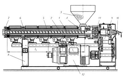
Figure 8. Single screw extruder
The basic arrangement of the single-screw extruder is shown in Fig. 8. The polymer material from the hopper 3 enters the material cylinder 2, is captured by the rotating screw 1 and is transported to the molding head, the fragment of which is shown at 7. In this case, the polymer in the first, feeding zone of the worm l1 softens and compacts in the plug, in the compression zone l2, it melts, and in the dosing zone l3 is homogenized and prepared for feeding into the molding head. To ensure the required thermal conditions and transportation conditions, zone ring heaters 5 with individual ventilation devices are mounted on the material cylinder; the cylinder section near the charging hole is cooled by water through channels 4 and thermocouples are used to control the temperature 6. The worm design usually provides its internal cooling with water supplied and discharged through the device 10. The worm receives rotation from an electromechanical drive consisting of an electric motor 12 of constant or alternating current and reducing mechanical transmission 9. The axial force acting on the worm in the direction opposite to the transport of the melt is perceived by the bearings th node 11. All working units of the extruder are mounted in the housing 8.
The technology of auger pressing is less and less used for the following reasons:
• high power consumption
• large wear of the feeding auger (mainly its first coils), which requires frequent replacement of the screw with new or surfacing on the working surface of the screw
• constant regulation of the screw gap during the operation of the press to ensure the identity of the quality of the briquettes produced
• need to cooling briquettes after pressing and heating
• a large heat loss and, accordingly, a low efficiency
For the reasons described above, the actual performance of such a press is always lower than the declared one. According to the experience of operation of extruders, their efficiency is 0.3–0.4, and for the maintenance of this press requires a fairly qualified staff.[7]
4.2 Crank presses
A crank press is a press in which the rotation of a drive motor through a crank mechanism is transmitted to a slide with a tool fixed to it. The tool is usually a stamp, the lower part of which (matrix) is on the desktop, and the upper (punch) – on the slider. Most often, crank presses are used for flat and bulky, cold and hot, stamping parts or cutting them, and also using crank presses, stretching, trim, chasing, pressing of powders and various types of bending are performed.
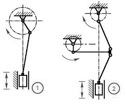
Figure 9. Schematic of crank mechanismsв
There is a lot of inclusion of crank mechanisms, in the inexpensive one-crank presses the crank-slider (Figure 9.1), an example of a functionally more complicated circuit, two-crank knee-slider (Figure 9.2) is most often encountered.
In powerful presses for more even distribution of load on the frame and desktop, two or more synchronously working cranks are used, this makes it possible to increase the linear dimensions of the stamp without loss in accuracy of the fitting of the punch to the die. In general, the crank press drive consists of an electric motor, a flywheel, a clutch, a brake and a downshift, by means of which the rotation is transmitted to the crank shaft. The electric motor unwinds the flywheel, which accumulates energy most of the time, and when the clutch is engaged, it gives it to the slider. Some crank presses are equipped with flywheels and gear gears of considerable mass and dimensions, these elements are carried to the sides of the press and covered with casings. More "advanced" models of crank presses have a compact drive, the elements of which are entirely inside the machine.
Crank presses can work in single-stroke mode (after one full stroke the clutch is disconnected), moving by jerks (repeated switching on / off of the clutch) or in automatic mode (the clutch is permanently on). The main technical parameters that characterize the crank press are its nominal force, the number of double strokes (full cycles) of the slider per minute, the length of the slider stroke, the slider stroke adjustment range, the size of the slider sole, the size of the working table, the open and closed height, the depth of the throat. The main advantages of crank presses before hydraulic: relatively low price, higher speed of operation, simplicity and maintainability.[8]
4.3 Hydraulic presses
Hydraulic presses use the force produced by hydraulic fluid pressure on the cross-sectional area of the master cylinder (or cylinders if there are several) to pressurize the workpiece. The force with which the hydraulic press presses on the workpiece is determined by the ratio of the working sections of the pump and the master cylinder. The number of times the force increases, the plunger speed is less than the rate of liquid injection in the hydraulic pump, so a more powerful hydraulic drive is required to ensure a higher speed. From this it follows that hydraulic presses have the greatest advantage wherever ultra-rapid movements of the slider are not required.
To increase the overall power and more even distribution of load across the bed, hydraulic presses can have multiple plunger and / or multi-cylinder design. Hydraulic presses are able to create a high force with relatively low power consumption, and therefore they are widely used for bending, straightening, cutting, baling, drawing, pressing powders, assembly press-fit operations, and also for "traditional" press operations – forging and forging.
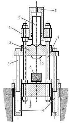
Figure 10. Schematic diagram of the column hydraulic press
In order for the tool 10 to work positively on the workpiece 9, the plunger 6 is pushed with compressed fluid (hydraulic oil or water-emulsion solution) supplied to the master cylinder 5. The plunger in turn pushes the movable crosspiece 3 which moves along the guide columns 7 , rigidly connecting the fixed upper 1 and lower 2 cross–members. To return the movable cross member to the initial upper position, the hydraulic actuator switches and starts feeding liquid into the return cylinders 4, pushing the plungers 8 upwards.
On most hydraulic presses it is possible to carry out briquetting of raw materials with humidity from 6 to 15%.
1. Научно-технический журнал «Обогащение руд»
2. Строительный справочник [Электронный ресурс].
3. Справочник по обогащению руд: Подготовительные процессы / Под ред. О.С. Богданова. Изд. 2–е, перераб. И доп. М.: Недра, 1982. – 366с.
4. Основы обогащения полезных ископаемых: Учеб. пособие для студентов вузов / В.В. Зверевич, В.А. Перов. М.: Недра, 1971. – 216 с.
5. Основы обогащения полезных ископаемых. Том 2. Технология обогащения полезных ископаемыхУчебник для вузов: В 2 т. –М.: Издательство Московского государственного горного университета, 2006. Т.2. –417 с. Авдохин В.М.
6. Дробилки.Конструкция, расчет, особенности эксплуатации. Клушанцев Б.В., Косарев А.И., Муйземнек Ю.А. М.:Машиностроение, 1990. –320с
7. Машины и агрегаты металлургических заводов. В 3–х томах. Том 3. Машины и агрегаты для производства и отделки проката. Учебник для вузов. A. И. Целиков, П. И. Полухин, В. М. Гребеник и др. 2-е изд., перераб. и доп. –М.: Металлургия, 1988. – 680 с.
8. Официальный сайт "RUF" [Электронный ресурс].