


Abstract
- Introduction
- 1. Theme urgency
- 2. The purpose and research problems, the planned results
- 3. Main section
- 3.1 Description of the manipulator design
- 3.2 Overview of the types of cut – off elements for entering the oxygen converter bath
- 4. Analysis of conducted research on the topic
- Conclusion
- References
Introduction
When producing steel in oxygen converter, a layer of slag is formed on the surface of the metal mirror, which, when the melting is discharged, enters the steel ladle. The presence of converter slag in the steelmaking ladle significantly reduces the quality of the produced products. The main negative consequences of slag from the converter entering the steel casting ladle are: an increase in the total oxygen content in the steel due to the high level of FeO and MnO in the slag; The slag forms a thick layer on the surface of the metal, which interferes with the operations for cut – off furnace metal processing in the ladle; there is a need to use machines for loading slag from the ladle; increase in the degree of rephosphorization, increased ferro – alloy fumes; increase in consumption of deoxidizers (aluminum, ferrosilicon, etc.); decrease in the service life of ladle lining [1].
Currently, metallurgical enterprises use such slag retention systems as: gas – dynamic slag cut – off system; with a slide gate valve; using the float type cut – off elements introduced into the cavity of the oxygen converter. According to the set of technical and economic indicators that allow to evaluate the effectiveness of the known methods of slag free steel production under conditions of oxygen – converter production, the most promising is the one that involves locking the outlet channel of the steelmaking unit with a special float type element introduced into its bath by means of a mechanical manipulator for input cut – off elements in the oxygen converter bath [ 2 ].
1. Theme urgency
To obtain high quality steel in an oxygen converter, it is necessary to minimize the amount of slag that enters the steel casting ladle when melting is produced. This remains an urgent task in modern converter steelmaking. One of the most effective ways to cut off the final converter slag is the use of float type cut – off elements, which are introduced into the bath of the converter by special mechanical manipulators. Revealing the most rational form of cut – off elements will increase the percentage of slag that is not allowed into the steel ladle, this problem is the subject of research into this master's work.
Master's work is dedicated to the actual scientific task of development a unified approach to the synthesis of Moore FSM, which is directing on hardware amount reduction in resultant device and is including algorithmic, combinatory and circuitry optimizing techniques. FPGAs by Xilinx, which combine functionality, programmability and availability to consumers, are used as the target basis. CAD Xilinx ISE, Verilog HDL and Java SE are applied as tools of the research.
2. The purpose and research problems, the planned results
Analyzing the existing types of cut – off elements, the features of their composition and application, it can be concluded that the most important task of further research is to determine the rational shape of the lateral surface of the cut – off element in the form arrows
which will allow to obtain high efficiency of slag cut – off, reduce costs when using "universal" elements and will allow producing cut – off elements using own production capacities.
As a result of the research it is planned to determine the most rational form of the lateral face of the head part of the cut – off element. By carrying out modeling of the process of slag cutoff on physical and virtual models of the oxygen converter.
The object of investigation cut – off of the final slag at the release of steel from the oxygen converter.
The subject of the study float type cut – off element of the oxygen converter introduced into the bath with a special mechanical manipulator.
3. Main section
3.1 Description of the manipulator design
Mechanical manipulators for the insertion of cut – off elements into the bath of the oxygen converter can be, for example, of their design, such as: suspension, telescopic, lateral and axial types (Fig. 1).
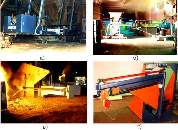
Figure 1 – Types of construction of manipulators: a – suspension type; b – the telescopic type; c – lateral type; g – axial type
However, the axial type manipulator (Fig. 1, d) developed by the department of mechanical equipment ferrous metallurgy plants Donetsk National Technical University
and protected by a patent [ 3 ], has a number the following advantages with respect to other types of manipulation systems, such as:
compactness and versatility of design use; high accuracy of positioning of the cut – off element in relation to the steel outlet before it is discharged into the bath of the oxygen converter; high reliability of work in extreme conditions of dustiness and high temperatures at the site.
This manipulator is located on a specialized work site, on the side of the steel outlet of the oxygen converter. In the initial position, this type of manipulator design does not interfere with the working space of devices for mechanical destruction of the worn liner of the converter, and also the shotcrete machines which are necessary for the repair of the lining. The manipulator has the ability to change the boom outreach distance, to facilitate adjustment of the coaxial positioning of the cut – off element with the converter's steel outlet.
The construction of the manipulator (Fig. 2) consists of a column 3 which is in turn mounted on fixed bearing supports, top 5 and lower 2. The column is rotated by means of drive 1. It is connected to the console 4, on which the bearing unit is mounted the vertical shaft 12, and at the end of this shaft is fixed the bracket 13, equipped with two guides, on which are located the rollers of the carriage 14, which ensure its movement along the guides. The carriage 14 carries a hollow rod 15, at the front end of which a float type cut – off element 16 is mounted by means of a spring lock. The rotation of the bracket 13 relative to the main arm 4 is produced by a mechanism consisting of a bevel gear 11 that combines the vertical shaft 12 with the rear end of the horizontal shaft 9 installed in the bearing supports 8 and 10. At the forward end of the horizontal shaft, a bevel gear 7 is mounted, which has the possibility of running in on the bevel gear 6, is fixedly fixed to the fixed upper support 5 of the rotary column 3
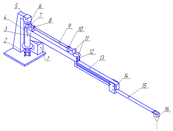
Figure 2 – Axle – type manipulator design: 1 – drive; 2,5 – lower and upper bearing supports; 3 – column; 4 – the console; 6 – Conical gear wheel; 7 – bevel gear, 8,10 – bearing supports; 9 – horizontal shaft; 11 – bevel gear pair, 12 – vertical shaft; 13 – bracket; 14 – carriage; 15 – the rod; 16 – cut – off element
With this manipulator design, the ratio of the number of tooth numbers of the conical fixed gear 6 and the bevel gear 7 is 2: 1. That ensures the simultaneous rotation of the column 3 with the console 4 to the required angle from the starting position, the relative rotation of the bracket 13 by 180 degrees, as a result of which the hollow rod 15 will be aligned along the coaxial axis of symmetry for any given variant of location of the technological equipment on the work site with the basic equipment of the main mechanisms (Figure 3). Such a design solution provides an increase in the level of universality of the manipulator design, bringing its structural nodes to a single standard and reducing the number of drives to one.
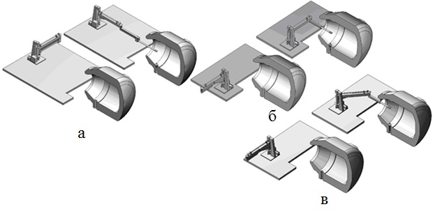
Figure 3 – Position of the links of the mechanical system of the manipulator in the initial and working positions with coaxial (a), lateral (b) and diagonal location on the site relative to the converter (c)
3.2 Overview of the types of cut – off elements for the introduction of the oxygen converter into the bath
The cut – off element is introduced into the oxygen converter's bath by a special mechanical manipulator after the converter has been tilted to the melting point of the steel ladle bucket. After its input, in order to perform its function, the cut – off element must have a special shape and a material density such that in the bath of the converter it is located at the interface between liquid steel and slag. At the time of completion of the steel, the cut – off element must lock the hole to prevent the final converter slag from entering the steel ladle. The above described process of slag cutoff is shown in Fig. 4.
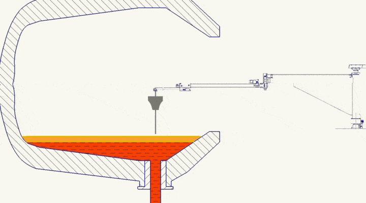
Figure 4 – Process of slag cutoff by a float type element. (The drawing is animated. Number of frames 8, size 141kb.)
Cut – off elements can be classified according to several characteristics: 1) according to the design, they can be in the form of a ball or arrows
(Fig. 5); 2) in size, depending on the volume of the converter; 3) chemical composition; 4) by the form of the lateral surface forming element for the element in the form of arrows
(Fig. 6).
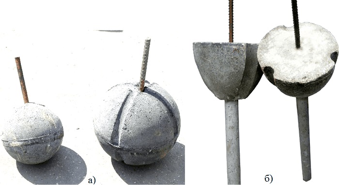
Figure 5 – Cut – off elements: a) in the form of a ball; b) in the form of the arrows
The manufacturer of cut – off elements the company Yuntian Metallurgy Technology Co., Ltd. gives some indicators of their physical and chemical composition. In addition to the chemical compounds mentioned: Al2O3, SiO2, Fe2O3 can also be included in the composition of materials. Scan the market of cut – off elements, we can say that the cost of one cut – off element ranges from 15 – 30 US dollars, without taking delivery into account.
The manufacturing process of the cut – off elements in the form of arrows
consists of the following steps: obtaining the necessary constituent materials, crushing and mixing, heating and shaping on special equipment, cooling, assembling the spherical part and the rod.
The use of different forms of cut – off elements is due to a number of factors. This is primarily the degree of effectiveness of the use of an element of a particular form. The effectiveness of slag cut – off with a refractory ball is less than 75%; The cut – off element in the form of the arrow
due to the guide rod ensures a cutoff efficiency of 90 – 98%.
The next factor of application is the cost of the elements. Despite the difference in the efficiency of the cutoff, the balls are still used, which can be explained by their relative cheapness compared to the "arrows", their cost differs by a factor of two. In addition, a significant factor is the physicochemical parameters of the cut – off elements, namely the ratio of the percentage content of the components that make up their composition.
This in turn affects the density of the material of the element and its location in the bath of the oxygen converter at the steel slag interface [ 4 ].
4. An analysis of the studies carried out on the topic
One of the factors that has a significant effect on the efficiency of the cutoff element in the form of the Analysis of the results of the study [ 6 ], states that for the cut – off elements having similar geometric parameters, the mass varies from 53.5 to 119 kg, the reduced density is almost the same and is about 2830..2860 kg / m3, the center of gravity is located at an altitude of about 0.9 m from the origin, and the depth of immersion in liquid steel has a wide range of variation.
The lowest values of the immersion depth are elements of type IV (the head part is a stepped cylinder), I (hyperballoid) and III (ellipsoid), i.e. The cut – off elements with this design will retain their equilibrium for a longer time as the level of liquid steel in the converter decreases during the discharge process and, ultimately, provides a higher degree of slag cut – off.
The obtained results of the calculations are consistent with the data of the studies carried out on physical models [ 7 ] and established that the most effective are variants of elements of types IV and III.
arrow has the form of a lateral surface (Fig. 6). As research shows [ 5 ], the irrational shape of the cut – off element can lead to premature cutting of the converter's steel outlet and, in addition, to an increase in the amplitude of natural oscillations.
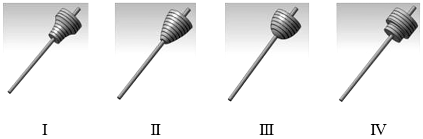
Figure 6 – Cut – off elements with different side surface shapes
Conclusions
In this abstract, the problem of cutting off final slag in oxygen – converter steel production was considered.
The highest percentage of slag cutoff is provided by float type elements, which are introduced into the converter cavity by a special mechanical manipulator.
It was definitely that the cut – off element in the When writing this essay, the master's work is not yet complete. Final completion: June 2018. Full text of the work
and materials on the topic can be obtained from the author or his supervisor after the specified date. arrow shape for the quality of slag cuts prevails over the ball – shaped element, in large part due to the guide rod and the shape of the side surface of the head part of the cut – off element.
From a survey of the studies carried out, it follows that further research should be devoted to developing the most optimal form of the cut – off element in the form of the
arrow . This actual task itself will be dedicated to this master's work
References
Механика жидкости и газа
. – Донецк: ДонНТУ, 2011. – С. 90–94.
Черметинформация
. Бюллетень Черная металлургия
, 2009. – Вып.6. – С. 39–45.