
Abstract
Content
- Introduction
- 1. The purpose and research problems, the planned results
- 2. Construction description
- 3. Main part
- Conclusion
- References
Introduction
In the steelmaking industry, there have recently been fundamental changes in connection with the replacement of the open-hearth method, the smelting of oxygen-converter steel, the creation of large converter aggregates, powerful electric steelmaking furnaces and new installations for special metallurgy, the development and wide application of continuous casting machines. In connection with the increase in the volume of production and improvement of the quality of steel, an extremely important role belongs to the oxygen-converter plant, which has high technical and economic indicators - high productivity with lower capital costs compared to the open-hearth method, more favorable conditions for automation. The capacity of one 400 tons of converter exceeds the capacity of the whole open-hearth furnace shop with 8-10 furnaces with a capacity of 600 tons each. The converter method of steel smelting is continuously improved. Modern technology of steel smelting in the converter provides for slag cut-off at the steel output from the converter. There are several ways of cutting off slag, for each of which special equipment has been designed and operated. In this paper, an axial-type manipulator is considered for inserting the cut-off elements into the converter's steel outlet channel for the release of steel.
1. The purpose and research problems, the planned results
The aim of the study is to improve the design of the manipulator to improve the reliability, study the temperature field of the manipulator acting on the rod in the oxygen converter. The main objectives of the study:
1. Studying the design of the manipulator and the heat field of the converter.
2. Development of mathematical model.
3. The experimental part.
4. Analysis of the results of the experiment.
5.Recommendations for practical use.
2. Construction description
The design of the axial-type manipulator for inserting the cut-off elements into the steel outlet of the converter when the steel is discharged is shown in Figure 1. This manipulator includes a vertical column 1 rotatably mounted in the lower 2 and top 3 fixed bearing supports and equipped with a bracket 4 on which the bearing assembly is mounted 5 with a vertical shaft 6. At the lower end of this shaft, the bracket 7 is rigidly fixed, having two longitudinal guides, in which are placed the rollers of the carriage 8, The locking mechanism of the bracket relative to the console includes a bevel gear pair 11 with a gear ratio of 1 connecting the vertical shaft to the rear end of the horizontal shaft 12 at the front end which is rigidly fixed to the bevel gear 13, which is able to roll over the bevel gear 14 [1]. This pinion is rigidly connected to the fixed upper support of the vertical column. And the ratio of the number of teeth of the fixed bevel gear and the bevel gear is 2: 1. These ratios of the structural elements of the bevel gears allow to automatically provide simultaneous rotation of the column with the console to a corner of 90 degrees, from the initial position the relative rotation of the bracket by 180 degrees, as a result of which the bracket and the bracket will be aligned in a line and occupy the coaxial position with the oxygen converter, kick is shown in (Fig. 1b). Subsequent delivery of the cut-off element to the zone of location of the converter's steel outlet channel (Fig. 1c) is carried out by moving the carriage with the hollow rod relative to the bracket using a chain drive [2].
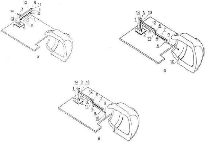
Figure 1 - Device axle type manipulator and its location elements in the initial (a), intermediate (b), and final (c) positions
3. Main part
The increasing demand for high-quality steel grades is a major problem for both metallurgists and metallurgical equipment designers. One of the most important tasks requiring a solution in the conditions of modern converter steel production is the reduction of the amount of the final process slag falling into the ladle ladle during the release of liquid metal from the oxygen converter. The effectiveness of the methods used to prevent the slag melt entering the ladle at the final stage of melting is largely determined by the technical capabilities of mechanical systems designed to cut off the final slag [3]. To cut off the final slag using elements of the float type, a special manipulator is used to insert the cut-off elements into the oxygen converter (Fig. 2). When you enter the float in the oxygen converter, all parts of the manipulator experience significant heat loads, under the most unfavorable conditions is the hollow rod of the manipulator. A high temperature can lead to deformation of the structure and lead to a deterioration in positioning accuracy, which is not an unimportant criterion when the float is thrown into the steel outlet.
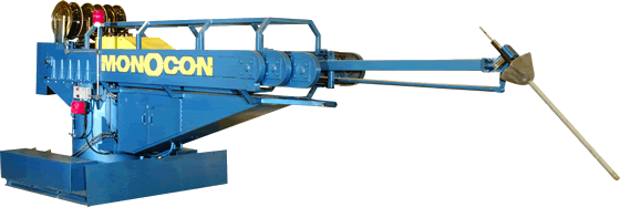
Figure 2 - Manipulator for the insertion of shut-off elements in the bath of the oxygen converter
One of the most loaded places in the manipulator to enter the cut-off element is its bar over which the experiment was conducted. The arm of the manipulator, on which the cut-off element is fixed, is structurally a pipe. During the process of entering the element into the bath of the converter, the rod is exposed to heat fluxes, which results in the occurrence of thermal stresses in it. The peculiarity of the manipulator is a cyclic repetition of actions, while the duration of the rod heating is 40 seconds, the cooling time is 40 minutes. Therefore, when designing the rod according to the strength criteria (material selection, cross-sectional dimensions), the cyclicity of the thermal action should be taken into account. In work [4] the mathematical model and results of calculation of distribution of temperature on cross-section of a bar are presented. Equally important is the knowledge of the temperature distribution along the length of the rod, which is supposedly uneven, caused by a different heat flux in the cavity of the converter and beyond. To confirm the proposed hypothesis about the nature of the temperature distribution along the length of the rod, experiments were conducted in a laboratory on a physical model. As a physical model of the rod, a stainless steel pipe with the following geometric parameters was chosen: outer diameter 24 mm, wall thickness 2 mm, length 450 mm. For 40 s in the electric furnace, which provides the temperature of the internal furnace medium at 250 ° C, the heating of the pipe section with a length of 200 mm was performed. The pipe was cooled in the open air at room temperature for 5 min. On the surface of the pipe, 9 control points were applied. The temperature was measured by a thermal imager. The measurement error was ± 1 ° C. The experiment included 5 cycles of thermal loading. Figure 3 shows the thermograms for the 1st and 5th heating cycles of the pipe, and Figure 4 shows the temperature variation along the length of the pipe after each heating cycle.
Figure 3 – The thermograms of the pipe after the 1st (a) and 5th (b) loading cycles
(animation: 6 frames, 5 cycles of repeating, 300 kilobytes)
Analysis of the measurement results showed that after the first injection of the tube into the furnace, the maximum heating occurs at a section of 150 mm. Here the temperature increased by 8 ... 24% relative to the initial state. The temperature in the section of the pipe located outside the furnace (300 ... 400 mm) remained practically unchanged. The central section is a transition from the zone with a high temperature to the zone with a lower temperature, therefore it is possible to form stress concentrators caused by a temperature drop. After the 2nd cycle of heating the pipe, a uniform increase in temperature along the entire length of the pipe is observed, by 5.4 ... 6.8%, relative to the values reached at the first input into the furnace. The third cycle of heating the pipe led to an increase in temperature by 2.3 ... 4.4% at the site introduced into the furnace. The temperature of the section of the pipe, which is located in the open air, practically did not change.
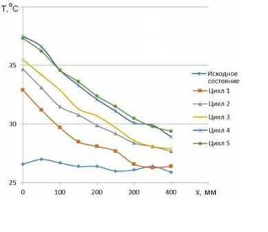
Figure 4 – The graph of the change in temperature (T) along the length (x) of the rod after each heating cycle
After the 4th input to the furnace, the temperature changed uniformly along the entire length of the pipe, the temperature increased by an average of 5.4%. The fifth heating cycle practically did not lead to an increase in temperature. In general, the maximum change in the temperature of the pipe occurs after the first heating cycle, although after the 5th heating the temperature increases by another 1.3 ... 1.6 times.
Conclusion
The obtained experimental data will be used in checking the adequacy of the mathematical model of temperature distribution developed by the author in the boom of the manipulator for inserting the cut-off elements into the oxygen converter while cycling it. This model will make it possible to clarify the concept of the stress-strain state of the rod and develop recommendations for choosing the optimal geometric parameters of the rod and steel grades for its production. When writing this essay, the master's work is not yet complete. Final completion: June 2018. The full text of the work and materials on the topic can be obtained from the author or his supervisor after the specified date.
References
- Опыт разработки систем отсечки шлака для сталеплавильных агрегатов / С.П. Еронько, А.Ю. Цупрун, С.А. Бедарев, С.В. Мечик // «Черметинформация». Бюллетень «Черная металлургия», 2007. – вып. 9, – С. 81 – 87.
- Еронько С. П., Смирнов А.Н., Кукуй Д.П. Разработка эффективных схем отсечки шлака при сливе металла из конвертера // Металлургическая и горнорудная промышленность. - 2003. - №8. - С. 33 – 37.
- Опыт разработки систем отсечки шлака для сталеплавильных агрегатов / С.П. Еронько, А.Ю. Цупрун, С.А. Бедарев и др. // ОАО «Черметинформация». Бюлл. «Черная металлургия» - 2007 - № 9 - С. 81 – 87.
- Исследование напряженно-деформированного состояния звеньев манипулятора для ввода отсечных элементов в выпускной канал конвертера / Еронько С.П., Ошовская Е.В., Бедарев С.А., Мечик С.В. // Металлургическая и горнорудная промышленность. – 2007.– №5. – С. 107 – 111.
- Теплофизические свойства веществ. Справочник / Под ред. Н.Б. Варгафтика. – Л.: Гос.энергетическое изд-во, 1956. – C. 367.
- Использование математического моделирования и САПР при разработке устройства устройства для отсечки конвертерного шлака / С.П. Еронько, Е.В. Ошовская, В.В. Киселев и др. // Прогрессивные технологии и системы машиностроения: Сборник научных трудов - Донецк: ДонГТУ, 2002 - № 23 - С. 52 – 56.
- Исследование напряженно-деформированного состояния звеньев манипулятора для ввода отсечных элементов в выпускной канал конвертера / Еронько С.П., Ошовская Е.В., Бедарев С.А., Мечик С.В. // Металлургическая и горнорудная промышленность. – 2007.– №5. – С. 107 – 111.