


Abstract
Содержание
Introduction
At present, there are practically no studies of fluid flows as a means of evacuation and transportation and the impact of force on bulk materials.
Let's analyze the existing methods of theoretical description of the hydromechanical effect force with the parameters of the coolant supply system to the cutting zone. In this connection, it seems relevant from a single theoretical standpoint to consider and establish the main regularities of the hydromechanical action of liquid jets on various bulk materials - metal and non-metallic shavings, destroyed coal, ores of various metals, etc. and on this basis to develop a methodology for determining the main parameters of devices intended for hydromechanical action on bulk materials.
1. Theme urgency
Intensification of the processes of metal machining, the introduction of high-performance equipment, automated processes, extensive study of structural materials lead to The fact that processing of metals by cutting often becomes impossible without the use of effective cutting fluids (coolant). Their application is a large and real reserve of improvement wear resistance of the abrasive tool, processing capacity and quality of the treated surface. [1,2]
The analysis of literature sources showed that only flooded continuous jets have been completely theoretically investigated, and which include jets propagated in a medium with the same density, viscosity and with the same physical properties. Unheated water jets have a density of liquid substance greater than the density of the medium (air) into which they flow, and the nature of the physical phenomena when the water out of the nozzles in the proposed technical solutions is different from those phenomena and regularities that occur in gas flooded jets. Therefore, in order to simulate the proposed systems with hydromechanical action of jets on bulk materials, it is necessary to establish and analyze the dependencies that make it possible to determine the main parameters of un-inflated jets.
2. Goal and tasks of the research
The aim of the study is to improve the stability of the grinding tool by controlling the characteristics of the coolant and its flow parameters.
The main objectives of the study:
- Test procedure for testing abrasive wheels and lubricating-cooling liquids during flat grinding.
- Development and investigation of an effective lubricating-cooling liquid for machining.
- The effect of various water-miscible lubricating-cooling techniques on the abrasive process. <
Research Object : the durability of the abrasive tool.
The subject of the study : the process of interaction between the abrasive tool and the workpiece under the action of lubricating-cooling liquids.
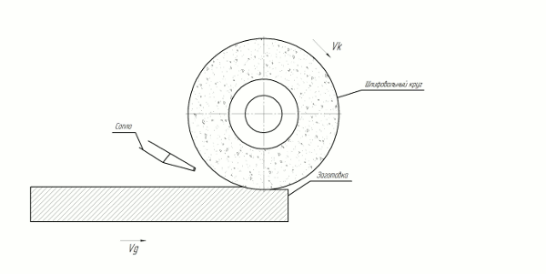
3. Main part
Test bench for studying the process of flat grinding. The stand includes a surface grinding machine mod. 3D71, dynamometer, tools for measuring the allowance and wear of the wheel, an optical attachment for monitoring the working surface of the wheel and the surface to be treated, a device for measuring the roughness of the treated surface.
The bench allows you to monitor the following parameters of the grinding process: the components of the grinding force (Pz , Py , Px ), wear of the wheel, deviation from cylindrical and circular surface of the working surface of the wheel, roughness of the treated surface without removing the sample from the table of the machine [3].
The dynamometer consists of a dynamometer UDM-100, an amplifier, an analog-digital converter and a personal computer. The dynamometer is mounted on the machine table and is fixed by a magnetic field.
The analog-to-digital converter is designed for converting an analog signal received in a dynamometer to a digital one and transferring it to a PC [4].
The values of the grinding force components are determined in volts. To translate them into newtons, the dynamometer is calibrated with a set of loads. Multiplying by the calibration factor the values obtained directly during the test, we obtain the desired force in Newtons. Calibration consists in loading the dynamometer with reference weights, fixing the resulting output signal from the ADC with subsequent statistical processing of the data. As a result, we obtain calibration curves for each of the components of the grinding force.
Before the start of testing, the limit of sensitivity of the dynamometer UDM 100 [5] was measured.
To determine the statistical error of measurements, it is necessary to know the minimum force that a sensing device can sense in a given installation. To do this, it is necessary to perform a series of repeated experiments consisting of successive loading of the dynamometer with standard weights of different weights (0.5 kg, 0.4 kg, 0.3 kg, 0.2 kg, 0.1 kg, 0.05 kg, 0, 04 kg, 0.02 kg). As a result of measurements it was established that the limit of the sensitivity of the force P z is 0.3 N g, and P y - 1 N [6].
Preparation for testing, in addition to calibrating the components of the grinding force, includes setting the wheel in the faceplate, balancing and correcting it. These actions are performed in the following order:
Mounting the grinding wheel on the faceplate;
static balancing before installation on the spindle of the machine;
setting the wheel on the machine spindle;
the primary correction of the wheel;
Removing the wheel assembly with the faceplate from the machine spindle;
final balancing of the wheel assembly with the face plate;
setting the wheel on the machine spindle;
Final rounding.
Testing includes [7]:
abrasive grinding of the metal layer from the sample by 0,01 - 0,03 mm per one table travel (table travel speed 12 m/min) with the use of coolant;
fixing the constituent forces on the PC; Measurement of wheel wear;
photographing the surface of a wheel;
measuring the roughness of the processed sample; photographing the sample;
Statistical processing of experimental data.
As shown by the statistical processing of experimental data, the optimal number of parallel experiments should be at least five.
Conclusion
Master's work is devoted to ensuring the stability of the grinding tool by controlling the characteristics of the coolant and the parameters of its flow. When writing this essay, the master's work is not yet complete. Final completion: June 2018. The full text of the work and materials on the topic can be obtained from the author or his supervisor after the specified date.
References
- Худобин Л.И. Смазочно-охлаждающие средства применяемые при шлифовании / Л.И. Худобин // Изд. "Машиностроение", Москва, 1971.
- Садыхов К.И., Гольдблюм М.А., Керимов Н.С. Смазочно-охлаждающие жидкости для алмазно-образивной обработки металлов / К.И. Садыхов // Изд. "Элм". Баку, 1978.
- Калафатова, Л.П. Влияние охлаждения на температурные и силовые параметры процесса шлифования, а также на качество поверхности ситаллов при различных режимах резания / Л.П. Калафатова, С.А. Поезд // Надежность инструмента и оптимизация технологических систем: сб. науч. трудов. – Краматорск: Изд-во ДГМА, 2008. – Вып. 23. – С. 194–201.
- Мамедова, П.Ш. Разработка и исследование эффективной смазочно-охлаждающей жидкости для механической обработки металлов / П.Ш. Мамедова // Нефтегазовое дело. – 2002. – Вып. 1.
- Никифоров, И.Н. Влияние различных водосмешиваемых смазочно-охлаждающих технических средств на процесс абразивной обработки / И.Н. Никифоров, В.Ю. Шолом, А.М. Казаков // Технология машиностроения. – 2006. – №7. – С. 22–25.
- Полетаев, В.А. Автоматизированные устройства для подачи смазочно-охлаждающей жидкости при глубинном шлифовании / В.А. Полетаев // Справочник. Инженерный журнал. – 2008.– №5. – С. 12–15.
- Фесенко, А.В. Повышение эффективности шлифования при гидродинамической обработке СОЖ / А.В. Фесенко, Ю.Н. Любимый // Вестник НТУ «ХПИ». – 2010. – №49. – С. 117–122.