
Abstract
Содержание
- Introduction
- 1. Theme urgency
- 2. Purpose and objectives of the study
- 3. Design and operation principle of hydraulic elevator
- 4. Feasibility of using a hydroelevator on the OP
Sh named. L.I. Lutugin
State EnterpriseTorezantratsit
- References
Introduction
At most (as well as in the OP Sh L.I. Lutugin
GP Torezantratsit
) of the main drainage systems, the scheme for the removal of solid impurities from mine water is as follows: before entering the water basin, clarification of water flowing along the drainage grooves of the mountain workings, in the preliminary clarifier. However, in some mines, water that is transported by gravity through open grooves or the soil of excavations falls directly into the main sump with a solids content of up to 10 kg / m3, of which 60-70% is abrasive. The basic system of a water outflow is a technological scheme periodically operating with discretely distributed time cycles, allowing sedimentation of a sludge in water collectors.
1. Theme urgency
Operation of the drainage system of the mine and in particular of the means for cleaning the drainage tanks is associated with many problems. The main of them are: insufficient quality of water clarification, the presence in it of an excessive concentration of solid impurities, often inadmissible size, often the water content of the reservoirs is higher than the established rate, significant costs of unskilled workers and time for cleaning the catchments. These problems can be solved by the introduction of hydrodynamic cleaning.
2. Purpose and objectives of the study
The purpose of the study is to increase the efficiency of cleaning underground tanks by using a hydroelevator.
Main tasks of the research:
- Analysis of literature sources regarding existing methods of cleaning mine tanks.
- The study of the basis of the theory of hydroelevators.
- Selection and justification of the parameters of the hydraulic elevator.
- Substantiation of energy-efficient methods of operation of hydroelevators.
3. Design and operation principle of hydraulic elevator
Figure 1 shows the scheme of the hydroelevator. The energy of the flow of the working fluid, which is fed through the pipeline of working water 1, in the nozzle 3 of the hydroelevator becomes the kinetic energy of the jet. A portion of this energy is used to move the fluid flow that is transported through the conduit 8 to the receiving chamber 2 and the confuser 4 before the commencement of the mixing chamber 5.
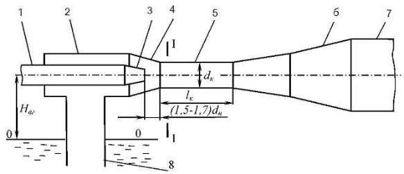
Fig. 1 - Diagram of hydraulic elevator
During the mixing of the flows in the mixing chamber, energy is transferred from the flow of the working fluid to the transported one. At the same time, the velocity of the working fluid decreases, and the transported fluid increases. The condenser serves to supply liquid that is transported, through the mixing chamber and to increase its speed, which reduces energy losses with mixing of the streams. In the diffuser 6, the kinetic energy of the mixed stream is converted into the potential energy of the pressure necessary to mix the flow in the pressure line 7 of the hydroelevator.
The simplicity of the hydroelevator design, the absence of surfaces that rotate and rub, provide a reliable and long-lasting operation on the contaminated liquid. The hydraulic operator has no need for qualified maintenance and constant presence of the person at the robot. When sucking in air, it does not need to be turned off, so it can pump out the water dry
. Due to these properties, hydroelevators are widely used in many industries. In the coal industry, they are used mainly to clean the skipstones of skip shafts and water collectors from solid material that is collected in them, hydrotransport of rock and coal, and vacuum dewatering.
Feasibility of using a hydroelevator on the OP Sh named. L.I. Lutugin
State Enterprise Torezantratsit
As a result of sedimentation of water in precincts, the concentration of solids is reduced to 300...200 mg/l, however, experience shows that the clarifying function of most water catchments is low. Accordingly, after clarification from the water collectors, it is necessary to remove the rock mass.
Negative consequences for mine drainage caused by the presence of impurities of solid particles in the mine water.
- Normal operation of pumps is possible only on clarified mine water with a content of mechanical impurities of not more than 0.1%, with a particle size of not more than 0.1 mm. In case of exceeding these values, which often takes place in practice, there is an increased wear of the flowing part of the pump.
- Reducing the volume of the water collectors, due to silting, leads to a decrease in their adjusting and emergency capacity, and the intervals between pump starts are shortened. Reducing the volume of the water catchment can lead to the impossibility of shutting down the drainage during the period of peak loads of the power systems.
- When the sump is clogged, the sludge enters the intake wells, which may result in overlapping of the opening of the safety net of the pump receiving device, which in this case will operate in cavitation and intensive wear mode.
- The precipitated sludge in the drainage tanks must be periodically removed, and more often by hand, since mechanical and hydraulic methods can not always be used in practice.
- Mine waters cause corrosion of pipe and armature material, and the degree of their impact is determined by the pH value, the content of ions H+, OH-, Cl-, Mg, etc., as well as dissolved oxygen. Especially dangerous for the construction of acidic and highly mineralized water.
The development of the coal industry proceeds along the path of increasing the concentration of mining operations, increasing the intensity of working areas and increasing the load on lava. This causes an increase in the daily inflow of water into underground mine workings, an increase in the amount of solid in the water and, as a consequence, an increase in the labor input for cleaning the drainage tanks.
One of the intractable technical problems of the coal mine OP Sh named. L.I. Lutugin
SE Torezantratsit
is the cleaning of underground catchment tanks, since it is produced manually.
There is a large number of possible ways and schemes for removing solid deposits from pouring tanks. Analyzing their conditions of underground mines, it was proved expedient to use hydraulic cleaning methods.
Consider the hydraulic method of cleaning the sump (Figure 3). It provides for the transportation of rock mass to the level of the near-barrel yard with the help of hydroelevators, coal pumps or slurry pumps, airlifts and loading devices.
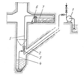
Fig. 3 - Scheme of cleaning the sump from a solid hydroelevator
The hydraulic water 3 from the shaft pump 1 is fed through the pipeline 2 with running water. By the supply line 4, the water, together with the solid from the sump, enters the hydroelevator and, through the pipeline 5, the slurry is supplied to the sludge accumulator 7. In the slurry tank, the clarified water flows through the branch pipe 6 into the groove and enters the sump. The thickened sludge is cleaned by the loading machine.
Advantages of this method are: continuity of the process, absence of any moving parts along the length of the pipeline, which ensures high reliability, simplicity and low labor input; continuity and low operationality of technological processes, which creates conditions for the automatic control of the transport system; it provides for joint execution by one technological link of operations for removing the waking rock mass, cleaning the catchment area of the sump from the sludge and pumping out the sump inflow.
Schemes for cleaning the sump using a hydraulic elevator provide for the extraction of rock directly from the catchment area of the sump, or from the collecting hopper. In this case, the pressure water for the hydraulic elevator is supplied, as a rule, from the discharge pipeline of the main water drain. The pulp is pumped to the horizon of the near-barrel yard, where separation of the solid is carried out at the dewatering facilities, sieves, etc. In some schemes, the pulp is pumped by the hydroelevator into the water basin of the main dewatering and, in others, to the coal sump, to the sludge accumulators, which use the lava space, or special workings in the vicinity of the barrow-court.
This master's work is not completed yet. Final completion: June 2018. The full text of the work and materials on the topic can be obtained from the author or his head after this date.
References
- Козиряцький Л.М., Спеціальні засоби i схеми гiдропiдйому, водовiдливу i очищення шахтних водовiдливних ємностей. // Навчальний посібник / В.М. Моргунов, В.М. Яковлев, О.А. Геммерлшг - Донецьк: ДонНТУ, 2012. - 133с.
- Матлак Е.С., Комплексный подход к решению проблемы нормализации работы водоотливного хозяйства шахт и охраны гидросферы по компоненту «Взвешенные вещества»// Научное издание «Проблемы экологии» (ДонНТУ)/ Т.И. Заика, А.И. Заика
- О повышении эффективности эксплуатации водоотливных установок / Практична електромеханіка та автоматика. Збiрник наукових праць / В.И. Самуся, И.Ю. Хиврич
- Папаяни Ф.А., Энциклопедия эрлифтов / Кононенко А.П., Козыряцкий Л.Н. и др. - Донецк, Москва: «Информсвязьиздат»,1995.
- Болотских Н.С., Исследования водоструйных насосов. Гидравлические машины. / Н.С. Болотских. – Респ. Межв. Сб., Харьков, 1973, вып. 7. – С.93-99.
- Безуглова Л.Н., Гидроэлеваторный способ очистки шахтных водосборников / Л.Н. Безуглова. – Уголь, 1983. – №4.
- Гейер В.Г., Гидравлика и гидропривод / В.Г. Гейер, В.С. Дулин, А.Г. Боруменский, А.Н. Заря. – М.: Недра, 1981. – 295 с.
- Семинская Н.В., Совершенствование гидроструйных технологий с учетом особенностей формирования струй высокого давления. // Автореферат диссертации [Електронний ресурс] /– Национальный техн. унив-т Украины– Киев: КПИ, 2008. – Режим доступа: http://www.dlib.com.ua/osoblyvostej-formuvannja.html
- Антонов Э.И., Эксперементальное иссследование сруйно-придонного течени на модели шахтного водосборника. - Научные труды НИИГМ им. Фёдорова, Донецк 2001г.
- Антонов Э.И., Совершенствование шахтных водосборнков / Шахтное строительство №5, 1986 г.