
Abstract
The contents
- Introduction
- 1. Actuality of the problem
- 2. The purpose and research problems, the planned results
- 3. Development of algorithm of diagnosing of a hydraulic drive of the refrigerator caster
- 3.1. General principles of diagnostic algorithms
- 3.2. Development of a mathematical model of the kinematic parameters
- References
Introduction
One of the final stages of the continuous casting of bars is their cooling. This operation is executed the special machine, urgent refrigerator. A refrigerator will realize the gradual moving and turning (revolution) over of square and round purveyances with the use of stepping beams. The drive of refrigerator is usually hydraulic.
In the process of exploitation refuses, related to the unevenness of wearing-out of hydro cylinders, losses of liquid,
deformation of constructions, begin in a machine to take place. This work will be devoted development of algorithm of
diagnostic ting of the technical state of hydraulic drive of refrigerator of CCM
.
1. Actuality of the problem
The construction of refrigerator (picture 1) consists of immobile 1 and mobile 2 beams, they are united between itself farkopom 3; hydro cylinders of the vertical moving 4 and hydro cylinders of the horizontal moving 5; purveyances 6.
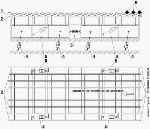
Picture 1. Chart of refrigerator of CCM
Experience in the operation of refrigerators of this design showed that after 5 years of work on the rise gradual and sudden cracks, like hydraulic drive elements and support structures.
The main requirements to the hydraulic actuator of the refrigerator of the continuous casting machine are synchronicity and stability of the cylinders, so the analysis of reliability of the drive is very important.
On the basis of the aggregate of the magazines for the 6-year period was carried out an analysis of the failure of the machine.
Figure 2 presents diagram of changes in the total annual number of failures of the refrigerator for the whole period of observation with the distribution of the seasons.
Here we can distinguish three intervals with different number of failures. For the first year – the minimum number of failures. During the next three years witnessed a steady annual number of failures. Over the last two years have seen a dramatic increase in the number of failures. This trend confirms the well-known pattern of changes of the failure rate of the machine as a complex system, we present an S-shaped curve and reflects the natural process of "aging" of technical objects.
The greatest number of failures (29,7 %) are connected to the hydraulic power unit and filters (28 %). Failures of hydro began to emerge after the first two years of operation, with a sharp increase in their number, and malfunctions of the filters took place throughout the period of observation, but significant rise in the intensity occurred at 5 and 6 years. The same trend is characteristic for pipes and accumulators (their share of failures of 15.3 and 11.9 %). Failures of hydraulic cylinders horizontal movement occurred annually, and they accounted for 7.6 %, and the bounce cylinders of the vertical displacement (5.1 per cent) began to emerge in the last two years. In the same period, noted the failures of threaded connections mounting the hydraulic cylinders (2.5 percent). In General, a significant increase in the number of failures in the hydraulic drive occurred at 5 and 6 years of operation, as for refrigerator caster in General.
The main types of failures of elements of the hydraulic drive are: cracked pipes, precipices high pressure hoses, defects in the fittings, weakening the torque flanged joints, wear and defects seals, membranes damage batteries.
For a detailed study of cause-and-effect relationships of failures and develop recommendations for improving the design of the refrigerator and the development of algorithm of diagnostics of its technical condition it is planned to develop a simulation model of a machine that can reproduce the movement of the machine to determine its kinematic and force parameters to monitor them in the event of various malfunctions of the hydraulic drive[4.]
2. The purpose and research problems, the planned results
The purpose of my work is development of algorithm of diagnosing of a hydraulic drive CCM. For this goal was:
- to perform the design of these machines;
- to analyze the types and reasons for faults of hydraulic drive;
- to develop a mathematical model of the kinematic parameters of the refrigerator and calculate the reference trajectory;
- calculate the forces acting on structural elements and hydraulic drive;
- build a physical model of the fridge to check the adequacy of the mathematical dependencies and allows to simulate possible malfunctions;
- develop sequence of operations for recognition of a technical condition of a hydraulic drive of the refrigerator.
3. Development of algorithm of diagnosing of a hydraulic drive of the refrigerator caster
3.1. General principles of diagnostic algorithms
Any task of diagnosis is solved with the implementation of the relevant procedure, which is based on the algorithm of diagnosis, which is a set of requirements in a sequence of checks and rules on the processing of their results. Distinguish the algorithms verify the integrity, performance, and Troubleshooting. There are three types of algorithms: unconditional unconditional stop conditional unconditional with conditional stop, conditional stop.
Unconditional algorithm selects a fixed sequence of inspections, with information about the technical condition of the object is recorded and processed consistently regardless of the results of previous audits.
In a conditional algorithm provides for the appointment of each subsequent inspection, depending on the result of the analysis of previous audits.
If the conclusion about the technical condition of the object can be made only after carrying out all the checks provided for by the algorithm, then this algorithm is called the algorithm with the absolute stop. If the results of diagnosing possible after each or some of the intermediate steps of the algorithm, the latter algorithm is called with a conditional stop.
The most common forms of representation of the diagnostic algorithms are table and tree graphs. Unconditional algorithms with unconditional stop are presented in the form of tables, which, for example, are the dictionaries of faults.
Unconditional algorithm with conditional stop is represented as a graph (Fig. 2A). The root node of the graph represents the set S={S1,S2,...,S7} of all the considered technical state of the object, and the remaining vertices - subset of States that is allocated by dividing the set S and its subsets according to the results of the elementary tests. Hanging vertices correspond to subsets of equivalent States. Originating from the peaks of the arches are depicted the unit test and setting arcs – the results of these audits.
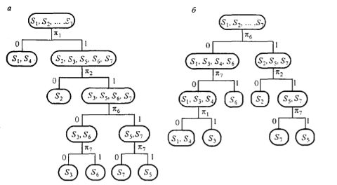
Fig. 2. Diagrams for unconditional (a) and conditional (b) of the diagnostic algorithms
3.2.Development of a mathematical model of the kinematic parameters
When developing mathematical models in the design of the fridge was the structural group constituting the linkage, the calculated diagram is shown in figure 2. Links AB and FE correspond to the cylinders for vertical movement, and link CD – hydraulic cylinder horizontal movement. Points B, C and E are located on the movable beam and moved blaskapelle. The edge lengths of CB, CE and VE are constant. Chetyrehdverny АВЕF forms parallelogram system. The position of each link mechanism at an arbitrary moment of time is characterized by the angle φi. When lifting and lowering the movable beams links AB and EF are of variable length, which depends on the speed of the cylinders, while the link CD is fixed in length and can be rotated around the point D. When the extension and retraction of the hydraulic cylinder horizontal movement changes the length of link CD link AB and EF have a constant length and making a rocking motion around points A and F respectively. In good mechanism lAB=lFЕ.
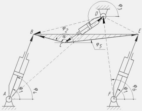
Figure 3. Design model linkage
Shown in Fig. 3 the mechanism was reduced to the generalized design scheme (Fig. 4).
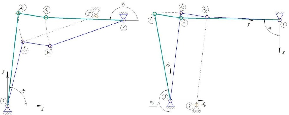
Figure 4 – Generalized design scheme for a four-bar mechanism during movement of the refrigerator lifting and lowering (a) and transfer-return to original position (b)
The position of the point 4 relative to point 2 in the process of movement is saved and can be described by distances:

Point 3 is the imaginary center of rotation point 2 – is given by the coordinates:


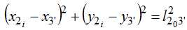
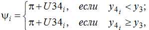
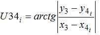
To determine the angle φi was considered the movement of the point 2, which moves along the arc of a circle with an imaginary center point 3’ with coordinates  and a radius
  , that is described by the equation:
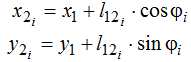
Point 2 belongs to link 1-2, therefore, its coordinates can be found from the expression:

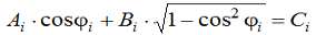
By splitting the terms and squaring the expression (8) is reduced to a square equation:

The found value of the angle ?i according to the formulas (5) and (6) are calculated the coordinates of a point 2, then the coordinates of point 4:
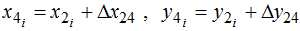
Dependences (1) – (15) form the basis of improved mathematical models for the determination of the position angles of links and trajectories of joints, linkage allocated in the structure of the refrigerator caster.
References
- Шамрай Ю.А. Математическая модель кинематических параметров холодильника МНЛЗ с шагающими балками / Ю.А. Шамрай, Е.В. Ошовская, В.А. Сидоров // Инновационные перспективы Донбасса, г. Донецк, 24-25 мая 2017 г. – Донецк: ДонНТУ, 2017. Т. 3: 3. Инновационные технологии проектирования, изготовления и эксплуатации промышленных машин и агрегатов. – 2017. – С. 113 – 118.
- Бойко, Ю.П. Конструирование машин для металлургических процессов / Ю.П. Бойко, О.С. Ануфриенко, Н.Я. Подоляк. – Орск: ОГТИ (филиал ОГУ), 2007. – 261 с.
- Сидоров, В.А. Эксплуатация гидропривода металлургических машин / В.А. Сидоров, Е.В. Ошовская, С.А. Бедарев: Учеб. пособие. – Донецк: эл.ресурс, 2015. – 252 с.
- Шамрай. Ю.А. Анализ отказов гидропривода холодильника МНЛЗ / Ю.А. Шамрай, Е.В. Ошовская, В.А. Сидоров // Механика жидкости и газа: материалы XV Международной научно-технической студенческой конференции, 28-30 ноября 2016 г., Донецк - Донецк: ДонНТУ, 2016. – С. 13–19.
- Попов, С.А. Курсовое проектирование по теории механизмов и механике машин / С.А. Попов, Г.А. Тимофеев. – Москва: Высш. шк., 1999. – 351 с.
- Липухин Ю.В., Данилов Л.И., Басов Г.А., Сорокин А.М. Холодильник для проката Патент РФ 2131315 1999г. Режим доступа: Ссылка
- Селезнев Н.П., Аксенов А.В.Способ транспортирования заготовок прямоугольного сечения Патент РФ 2016363 Режим доступа: Ссылка
- А.И. Савельев, С.В. Козлов, Д.О. Анисимов - Особенности формирования динамических моделей многодвигательных гидроприводов мнлз // СибГИУ УДК 621.01:669.02/09 c.28-31 Ссылка