
Abstract
Content
- Introduction
- 1. Theme urgency
- 2. Goal and tasks of the research
- 3. The device and the principle of operation
- 4. Mathematical model of the workflow
- Conclusion
- References
Introduction
The main way of conducting overburden, mining and auxiliary works with the help of a pressure jet of water are hydraulic monitors, which serve to create a dense, compact jet and control its flight during erosion and excavation of rocks, ores, building materials, placer deposits and mineral deposits [10].
Scientists of various research and higher educational institutions have proved that the alternating pulsating action of water jets on a mountain massif is much more effective than a stationary one. The double-barrel pulse hydromonitor GI-4 (designed by DonNTU) converts the stationary flow of water into two pulsating water by switching through the passage channels. The main part of this device is the flow converter, which is a complex non-linear dynamic system. Its working processes depend both on the design and operational parameters of the installation and only with the correct ratio of them are possible stable and adjustable self-oscillating operating modes.
An analytical solution to the problem of choosing optimal relationships between the parameters of the system from the point of view of the performance of the hydromonitor is not possible, since there is no derivation of indicators of the quality of the working process in a form suitable for mathematical analysis [8]. Therefore, the study of the working process of a double-barrel pulse monitor was carried out using mathematical modeling methods.
1. Theme urgency
The use of hydraulic monitors for coal mining ensures low operational efficiency, safety and simplicity of processes. In the construction of hydroschemes, a smaller volume of capital expenditures and a shorter time for their commissioning are needed, in contrast to the mechanical design of coal seams [9]. The use of hydraulic monitors with a flow converter will increase the productivity of hydraulic breakers and their use in the mining industry, which is an urgent task.
2. Goal and tasks of the research
The purpose of this paper is to analyze the converter of the pulsed water jet flow, to determine its optimal operating parameters and to improve the design to improve the efficiency of coal hydro-mining.
3. The device and the principle of operation
The schematic diagram of the flow converter is shown in Figure 1. It consists of a body 1, a piston group 2 comprising two pistons rigidly connected to each other by a rod, trunks 3 and 4 with nozzles of the same diameter, transfer tubes 5 and 6, air chambers 7 and 8, between the detachable flanges of which are installed diaphragms 10 and 11, separating the air and the plug-in cavity, the control valve 9 with a discharge hose.
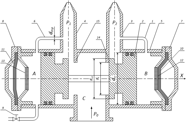
Figure 1 – Schematic diagram of the flow converter
The principle of the converter is as follows. In the initial position, the control valve 9 is closed. Water from the main pipeline enters the interspace C, trunks 3, 4 and through the nozzles expire into the atmosphere. Part of the water in the transfer tubes 5 and 6 fills the shut-off cavities A and B, compressing through the diaphragms 10 and 11 the air under excessive pressure in the chambers 7 and 8. The system is balanced, the piston group 2 is on average with respect to the seats 14 and 15 position. If the control valve is opened, the water pressure in the cavity A decreases, the piston group moves to the far left position and closes the barrel 3. Since the cavity B through the transfer tube 5 and the trunk 3 is connected to the atmosphere, the pressure in it will gradually decrease, and the part of the volume of water is squeezed out by the compressed air of the chamber 7. Once the diaphragm 10 is lined on the grate 12, the pressure in the cavity B will drop to atmospheric.
If the control valve is closed at this time, the pressure in the cavity A increases, and due to the difference in forces acting on the piston group, the latter will move to the extreme right position, close the barrel 4 and open the trunk 3. In the cavity A, the pressure will gradually decrease until the diaphragm 11 will not come into contact with the grate 13. Simultaneously, water from the barrel 3 through the transfer tube 5 fills the cavity B, compressing the air of the chamber 7. When the diaphragm 11 comes into contact with the grill 13 in the cavity A, the pressure drops to atmospheric pressure and in the cavity B reaches its poppy of the sim- ilar meaning. There will be a redistribution of forces acting on the piston group, and the latter will move to the left end position, while the trunk 3 will be closed and the trunk 4 will open.
Then the process repeats, the flow converter enters the auto-oscillation mode. In this case, the alternate flow of liquid through the trunks 3 and 4 is observed, that is, the supplied continuous liquid flow is converted into two pulsating ones.
The converter can also be started in the self-oscillation mode when the control valve is open at the initial time. Then the outflow of the liquid occurs only through the barrel 4, and if the control valve is closed, the working process will be repeated in the same way as previously considered.
To output the converter from the self-oscillating mode, it is necessary to open the control valve, with the piston group occupying the leftmost extreme position, and the liquid will flow only through the barrel 4.
The operating principle of the pulsed flow monitor is shown in Fig. 2.

Figure 2 – The work of the converter of the flow of the pulse jet monitor
(animation: 14 frames, 10 cycles, delay between frames 0.5 sec, 72 Kb)
4. Mathematical model of the workflow
To obtain a generalized mathematical model of the flow converter, we will compose equations describing the dynamics of its individual links, taking into account the main parameters of the installation: the geometric dimensions of the nozzles, transfer tubes, valve pair, mass of the piston group, pressure losses in the transfer tubes, on the valve pair and in the air chamber grilles.
The flow converter will be conditionally divided into two parts – movable and fixed. The fixed part includes a body with valve seats, barrels and nozzles, transfer tubes and air chambers, and a movable part includes a piston group consisting of a rod and two pistons with seals.
For the description of the working process, we distinguish in the design of the converter two control cavities A and B, as well as an intersection chamber C, into which water flows from the supply pipeline (see Figure 1).
We assume that at the initial instant of time there is a steady state in the system: the piston group is in the extreme left position and the flow of the liquid expires through the left trunk 4.
The relationship between water flow through the left barrel Q1 and the applied pressure P0 is described by the equation:
 |
(1) |
where – water density, kg/m3; g – acceleration of gravity, m/s2; ak1, an1 – hydraulic resistance of the left valve slot and left-hand nozzle, s2/m5;
Pressure Р1 before the nozzle of the left valve is determined by the dependence:
 |
(2) |
As shown by the analysis of studies performed by G.V. Dotsenko [1], the value of the coefficient of hydraulic resistance at an unsteady pressure depends on the viscosity of the fluid, the value of local resistance and frictional resistance, and the effect of the latter increases with increasing nonstationarity of the flow. In the systems under investigation, the working process with a frequency of 5 – 20 Hz ripples can not be considered high frequency, water is a low-viscosity liquid, and frictional resistance is insignificant in comparison with local resistance; therefore, in calculating the dynamics of a turbulent flow, the coefficient of hydraulic resistance is assumed equal to its value for steady motion.
Hydraulic gap resistance between valve and seat ак1 can be determined by the formula for poppet valve [2]:
 |
(3) |
where dкл – valve diameter, m; X – elevation of the valve above the seat, m; μщ – coefficient of flow, variable value and depends on the height of the lift of the valve, its shape and to a lesser extent on the structural dimensions.
A number of authors [2, 3, 4] have established the dependence of the flow coefficient μщ – from the dimensionless parameter A, representing the ratio of the valve slit area Sщ to the cross-sectional area of the saddle hole Sc:
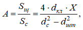 |
(4) |
where dc – seat diameter, m; dшт – stem diameter, m.
Based on the design dimensions of the flow converter, the conditions of strength, tightness and practice of operation of the valve pair, and taking into account the recommendations [3, 4], we take dc = 0,8dкл, dшт = (0,35…0,4)dкл.
After simple transformations we get the expression:
 |
(5) |
The value of the coefficient μщ depending on the dimensionless parameter A, is determined from the graph (Figure 3), constructed from data [3] for structurally similar valves.
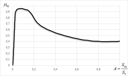
Figure 3 – Dependence of the coefficient of flow of the valve slot on the dimensionless parameter A
According to the data [2] the hydraulic resistance of a valve pair depends on its geometric dimensions and design, and formula (3) is obtained for a flat poppet valve, to which the liquid is pumped and discharged along its axis. The valve we examine differs from the one considered in [2] by the presence of the rod, the lateral approach and the discharge of the liquid. In theoretical studies, this difference was not taken into account, since X = 1 ... 3 mm is not the working range of opening the gap.
To derive the equations of motion of the piston, the following assumptions are made:
- the forces acting on the piston are directed only parallel to the X axis, the positive direction of which is shown in Fig. 1;
- when moving in both directions, the piston reaches the stop, where its speed is extinguished to zero;
- the frictional force of the cuffs is directed opposite to the velocity vector of the piston;
- the elasticity of the seats is negligible.
The left piston is under the action of the following forces: РА⋅Sп – the force acting on the left piston from the side of the cavity A, N; (P0+P1)⋅Sкл/2 – force acting on the area of overlap of the left valve with a seat, N; fy⋅Sy⋅|PA-P1| – force of friction acting on the left piston, N.
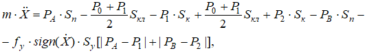 |
(6) |
where m – mass of piston group, kg; Sкл=π/4⋅(dкл2–dс2) – valve overlap area, m2; Sк=π/4⋅(dп2–dкл2) – annular area of the valve, m2; Sy=π⋅dп⋅h – cuff area, m2; dкл, dc, dп – the geometric dimensions of the valve, seat and piston, respectively (see Figure 1), m; fy – coefficient of friction of the cuff; h – working height of cuff, m.
To account for the friction effect of sealing cuffs, the friction coefficient fy of the steel-rubber pair is introduced into the equation (6). In the converter, the cuffs work under specific conditions: pulsating multi-cycle pressure, uneven reciprocating motion, water contamination with abrasive inclusions, corrosive fractures on the sealing surfaces. The complex effect on fy of the listed factors has not been studied enough, therefore, the friction coefficient of the cuffs was determined experimentally and in subsequent calculations it was assumed to be constant and equal to its mean value.
In the control cavity А, the pressure PA is related to the pressure in the barrel by the following relationship:
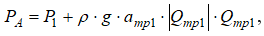 |
(7) |
where aтр1 – hydraulic resistance of the tube 6, s2/m5; Qтр1 – alternate flow through a transfer tube, m3/s.
When the flow converter is operating in air chambers, processes of a rapid change in air volume with a frequency of 5 to 20 Hz continuously occur. Therefore, taking into account the results of the research [2], it can be assumed that the change in the pressure in the air cavity of the chambers obeys an adiabatic law.
 |
(8) |
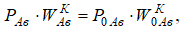
where PAв – current air pressure in the left chamber, Pa; P0Aв – initial air pressure at the initial geometric volume of the chamber W0Aв, Pa; WAв – current volume of air in the chamber at pressure PAв, m3; K – adiabatic index (K = 1,41).
The relationship between pressure PA and PAв taking into account the hydraulic losses during the flow of water through the confinement grid 12, is expressed by the following relationship:
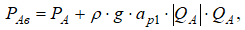 |
(9) |
where aр1 – limiting grid resistance, s2/m5; QA – fluid flow in the control cavity А, m3/s.
From the conditions of the flow balance in the control cavity А:
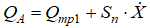 |
(10) |
Here Sп=π/4⋅dп2 – piston area, m2; X' – piston travel speed, m/s; X – piston coordinate, m; Sп⋅X' – flow rate of liquid displaced by the piston as it moves, m3/s.
Now it is not difficult to establish a connection between the air volume in the chamber and the flow of liquid through the lattice:
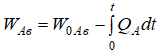 |
(11) |
It is known that the unsteady movement of water in the barrel is described by a system of two partial differential equations including the equation of continuity of the flow and the Euler equation supplemented by a term that takes into account losses:
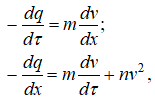 |
(12) |
where q – relative change in pressure; ν – dimensionless speed; τ – dimensionless time; x – coordinate of the section; m – criterion of the trunk; n – relative pressure losses in the barrel.
The last term of the second equation takes into account the pressure drop along the length of the barrel. For pipelines as trunks of a hydromonitor, distributed resistance can be neglected and considered conditionally concentrated at the flow converter. In this case, the pipeline acts as a link with a clean lag.
If we assume that the change in the reduced resistance of the system occurs instantaneously, then the duration of the wave processes in the system is characterized by the time of the double path of the wave from the hydrostatic, i.e., t = 2⋅L/C. When the flow converter is operating, the life time of the pressure pulse is 0.05 seconds. The length of the barrel L is 0.7 m, the speed of propagation of the wave from the hydraulic shock is C = 1300 m/s, then the time of the double run of the wave is t = 2⋅0.7/1300 = 0.001 seconds.
The time of existence of a wave from a hydrodisturbance is 50 times shorter than the time of the existence of a pulse and thus is within the accuracy of measuring devices. Consequently, its influence on the operating mode of the converter can be neglected. Therefore, when considering the operating mode of the converter, the wave processes are not taken into account.
Conclusion
The principle of operation of the piston flow converter, which provides the self-oscillating mode of operation of the two-armed pulse hydromonitor, is considered. The installation works due to the moving water flow and does not require additional energy sources.
Further work is aimed at creating a more perfect design in which there will be no rubbish parts, which will reduce the power consumption of the installation and increase the frequency of self-oscillations. The mathematical and simulation model for the new design will provide the opportunity to select the optimal operating parameters of the converter.
When writing this essay, the master's work is not yet complete. Final completion – June 2018. Full text of the work and materials on the topic can be obtained from the author or his supervisor after the indicated date.
References
- Доценко Г.В. Оптимизация параметров гидроимпульсаторов горных машин. Дис. … канд. тех. наук. – Донецк, 1979. – 331 с.
- Идельчик И.Е. Справочник по гидравлическим сопротивлениям / Под ред. М.О. Штейнберга. – 3-е изд., перераб. и доп. – М.: Машиностроение, 1992. – 672 с.: ил.
- Караев М.А. Гидравлика буровых насосов. – М.: Недра, 1975. – 183 с.
- Верзилин О.И. Современные буровые насосы. – М.: Машиностроение, 1971. – 256 с.
- Голдынский Г.Г. Разработка и исследование двуствольного импульсного гидромонитора. – В сб.: Совершенствование технологии, средств комплексной механизации, автоматизации и техники безопасности при подземной разработке угля. Тезисы докладов. – Караганда.: КНИУИ, 1978, с. 69-70.
- Гейер В.Г., Дулин В.С., Боруменский А.Г., Заря А.Н. Гидравлика и гидропривод. – М.: Недра, 1981. – 296 с.
- Шавловский С.С. Основы динамики струй при разрушении горного массива. – М.: Наука, 1979. – 174 с.
- Экбер Б.Я., Маркус М.Н. Анализ техники и технологии гидравлической добычи угля. – М.: ЦНИЭИуголь, 1974. – 85 с.
- Тимошенко Г.М., Исадченко В.С., Голдынский Г.Г., Кравец В.Г. Двуствольный импульсный гидромонитор. – Уголь Украины, 1978, №12, с. 23-24.
- Гидромониторы. Кат. – машины для гидромеханизации земляных работ // [Электронный ресурс]: Строительные машины и оборудование, справочник. URL: http://stroy-technics.ru/article/gidromonitory