
Abstract
Content
- Introduction
- 1. Goal
- 2. Description, purpose and principle of the installation
- 2.1. Milling machine for processing edging sheets such as PFM90 / 600 CNC
- 2.2. Milling process
- 3. Used electric drives and control principle
- 3.1 Asynchronous motor transients
- 3.2 Asynchronous motor control
- 3.3 Permanent magnet synchronous motor control
- 4 Output
- References
Introduction
Numerical control (abbr. CNC; Eng. computer numerical control, abbr. CNC ) – the field of technology associated with the use of digital computing devices to control production processes. [ 5 ]
CNC equipment can be represented:
- machine park, for example, machines (machines equipped with numerical control, are called CNC machines) for machining metals (for example, milling or turning), wood, plastics;
- asynchronous motor drives using vector control;
- characteristic control system of modern industrial robots;
- peripherals, such as a 3D printer, a 3D scanner.
The CNC abbreviation corresponds to two English-speaking – NC and CNC.NC – Numerical Control. CNC – Computer Numerical Control.
The first obvious advantage of using CNC machines is a higher level of automation. Cases of intervention of the machine operator in the process of manufacturing parts are minimized. CNC machines can work almost autonomously, day after day, week after week, producing products with consistently high quality. In this case, the operator’s main concern is mainly the preparatory and final operations: installation and removal of the part, adjustment of the tool, etc. As a result, one worker can operate several machines at once. The second advantage is production flexibility. This means that to process different parts you only need to replace the program. And an already tested and tested program can be used at any time and any number of times.
The third advantage is high accuracy and repeatability. According to the same program, you can produce thousands of almost identical parts with the required quality.
Finally, numerical control software allows you to handle such parts that can not be made on conventional equipment. These are parts with complex spatial shapes, such as dies and molds. [ 6 ]
1 Purpose of Work
The purpose of my master’s work is to familiarize and study the principle of operation of the machine with numerical control. The main task is the mathematical description and modeling of the operation of asynchronous and synchronous motors with permanent magnets of a CNC milling machine, the study of transients, and the analysis of the results of the installation.
2 Description, purpose and principle of the installation
2.1 Milling machine for processing edges of sheets like PFM90 / 600 CNC
The milling trimmer is designed for processing sheet steel. It works on the basis of a high-speed method of milling developed by the company, in which peripheral mills are used.
Thanks to this method, very high feed rates are achieved, and a variety of profiles are processed in a single pass using the profile milling heads.
The milling heads are equipped with carbide swivel cutting blades.
Since the sheet being processed is in most cases wavy, and the milled chamfer should remain unchanged along the entire length of the sheet, the milling devices have copy rollers for transverse copying.
Sheet metal edge milling machine is a production unit on a single line for continuous machining.
The sheets to be processed are placed on the loading table precisely centered with respect to the milling devices.
The centering device centers and positions the sheets.
The transport system for sheets consists of a transport trolley on which clamping collets are located, where one of them is adjustable depending on the length of the sheet.
On a transport cart, the sheets are clamped on each side in the middle.
After the sheet is clamped with the clamping collet, it is transported through the milling devices installed to the right and left of the longitudinal guide, and its longitudinal sides are processed.
After measuring the width of the sheet and determining the depth of cut, the maximum feed rate is calculated automatically.
If the cutting depth is too large or the sheet is not wide enough, the management system sends a corresponding warning.
After the sheet has been machined, the clamping collets on the transport cart are unclamped and the sheet is laid on the unloading table located behind the milling devices, designed for transporting sheets. It is possible to remove chips that are not removed at the time of transportation by means of a single chip brush with its own drive.
After that, the transport cart returns to the starting position in an accelerated course and takes the next waiting list. This sheet was set and positioned during the milling process of the previous sheet.
Figure 1 – Structural scheme of milling machine
(animation: 6 frames, 51.5 kilobytes)
Designation and purpose of the axes of a CNC milling machine:
- SS1 – Switch cabinet – Electrical Cabinet
- P1 – Control desk – Control panel
- FL – Miller left – Milling grandma on the left
- FR – Miller right – Milling grandma on the right
- ZFL – Feed in milling unit left – Supply milling headstock on the left
- ZFR – Feed in milling unit righ – Supply milling headstock on the right
- BFL – Strip guiding left – Plate guide left
- BFR – Strip guiding right – Plate guide on the right
- RBR – Aligning beam right – Right centering line
- RBL – Aligning beam left – Left centering ruler
- VFZ – Movable tong – Mobile Collet
- TW1 – Feed carriage 1 (Master) – Transport Trolley 1 (Lead)
- TW2 – Feed carriage 2 (Slave) – Transport Trolley 2 (Slave)
2.2 Milling process
- The sheet is laid with a workshop crane on the roller conveyor longitudinally;
- The sheet is brought to the position by drive roller tables;
- All the collets on the trolley are open;
- From positioning the transport cart;
- From positioning the sheet in front of the transport cart; for subsequent work, lay and position the next sheet on the loading table;
- Return the vehicle to its original position;
- Align the sheet using the centering beam parallel and centered;
- Close the extreme collet;
- Close the movable collet;
- Open the centering beam;
- Drive milling heads, chip conveyors and chip brushes;
- The transport car rides with the start of the sheet inside the first roller of the guide strip of the milling device (if the roller table is free);
- Lower the strip guide;
- Milling feed through the transport trolley: the sheet is milled to the left and to the right (the finished sheet from the unloading roller table moves to the live rolls);
- The end of the sheet reaches the last roller of the guide strip of the milling device: fix copying (mill the end part);
- During this course of milling, the next sheet comes in position before focusing on the sheets;
- The rollgang brings the sheet to the stop;
- Align the sheet with a centering beam along the parallel and center;
- The transport trolley positions the milled sheet on the unloading roller table;
- Open the movable and extreme collet;
- Transport guide strips vertically;
- The trolley returns to position 0;
- Further work as in clause 12 and following;
- For a piece list: end of processing.
3 Used electric drives and control principle
Most of the axes of this setup move and position using permanent magnet synchronous motors (SPDM). The cutter drive is driven by an asynchronous motor. The drives are controlled using SINAMICS S120 type control units.
The electronically coordinated individual drives together solve a common problem. The top-level control system drives the drives in such a way that the desired coordinated movement occurs. This requires cyclical data exchange between the control module and the drives. The central control unit performs the control functions for all drives connected to it and additionally implements the technological links between the drives. Responsible connections are implemented within one block and are simply designed using one STARTER commissioning tool with one click of the mouse. Simple technological tasks independently solves the SINAMICS S120 control unit. For individual drives there are separate control modules CU310 DP or CU310 PN. For multi-axis applications, there is a control module CU320
Each of the control modules is based on the SINAMICS S120 object-oriented software standard, which contains all common controls, with the ability to scale to the highest performance requirements. Ready-made drive control units are available as configurable objects: for power modules Infeed Control
, for a wide range of asynchronous motors Vector Control
and for dynamic applications and synchronous motors with excitation from permanent magnets Servo Control
. All these methods of regulation are based on the principle of vector control with orientation along the magnetic field vector. Common U/f controls are found in the Vector Control
drive object and can also be used to optimally solve simple tasks, such as group drives with SIEMOSYN engines. [ 4 ]
3.1 Asynchronous motor transients
To track the transients, an asynchronous motor scheme was developed in the orthogonal coordinate system in the MatLab environment of the Simulink library. A model of an asynchronous motor in an orthogonal coordinate system oriented along the rotor flux linkage under conditions of power supply from a voltage source is shown in Figure 2.
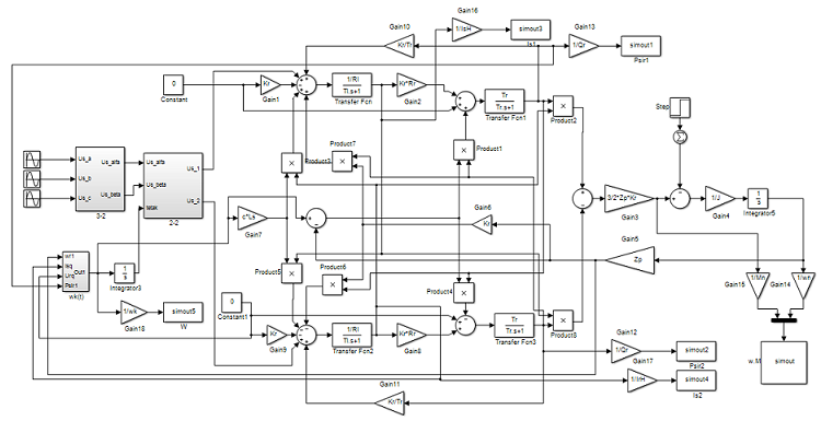
Figure 2 – model of asynchronous cutter drive motor with rotor flux orientation
Figure 3 shows the transient characteristics of the moment and speed with a nominal torque ramp.
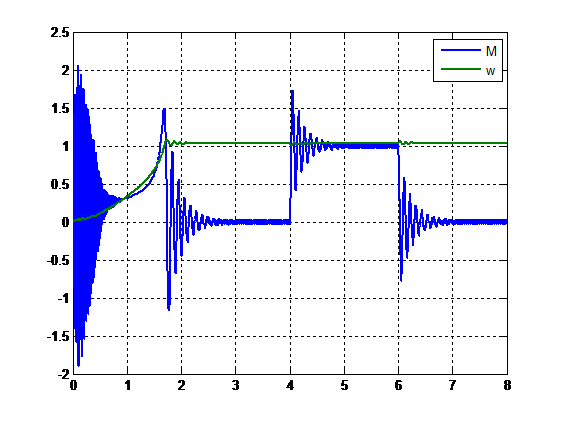
Figure 3 – graph of the moment and speed of the asynchronous engine
Figure 4 shows a graph of ωk with orientation along the flux link vector
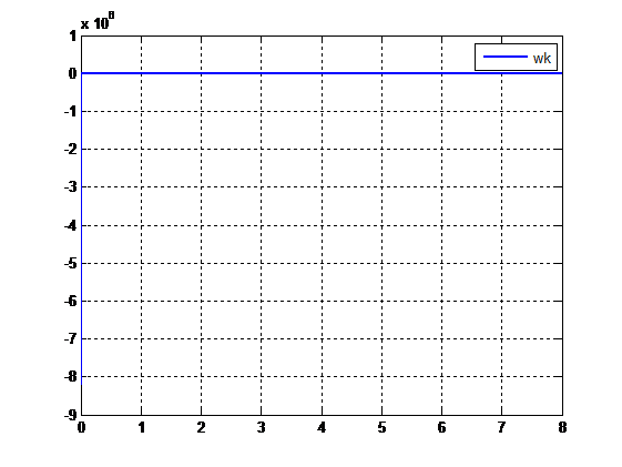
Figure 4 – graph ω \k oriented on the rotor flux linkage
A graph of the flux linkage between the rotor and the stator is shown in Figure 5.
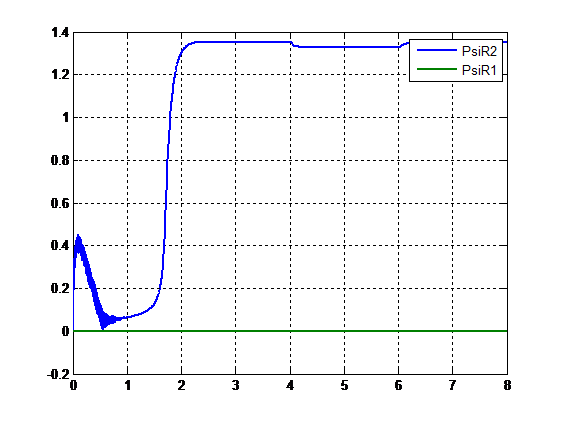
Figure 5 – rotor and stator flux link graph
Figure 6 shows the graphs of the stator and rotor currents at rated load.
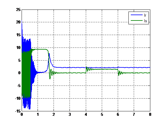
Figure 6 – graph of stator and rotor currents
3.2 Vector control of an asynchronous motor
With vector control, control is based on instantaneous variable values. In digital vector systems, control over equivalent (averaged over the discrete interval of control) variables can be performed.
Vector control is designed to ensure the law of frequency control Ψr = const, therefore, the desired static and dynamic properties of the EA by using distributive regulation of mechanical (moment, speed) and magnetic (magnetic flux or flux linking) coordinates while vector control takes into account the mutual position of the generalized electromagnetic vector vectors. [ 3 ]
Implements the principle of orientation of vector variables with respect to each other. In particular, the orientation of currents and voltages relative to the rotor flux linking vector has become widespread. Orientation provides separate (independent) control of torque and flux linkage in dynamic and static operating modes of the drive.
Explicitly or implicitly, there is a control circuit of the electromagnetic torque of the engine. In the first case, the principle is implemented
direct control of the moment. The corresponding vector control systems are referred to as direct moment control systems. In the traditional
vector control systems with the stator current orientation along the rotor flux linkage vector, the role of the moment contour is performed by the closed contour of the active component of the stator current. [ 2 ]
Thus, to build a vector control system for blood pressure, you need to choose a vector relative to which the coordinate system will be oriented, and the corresponding expression for the electromagnetic moment, and then determine the values included in it from the equations for the stator and rotor circuit.
Figure 7 shows the functional diagram of the vector control system for blood pressure
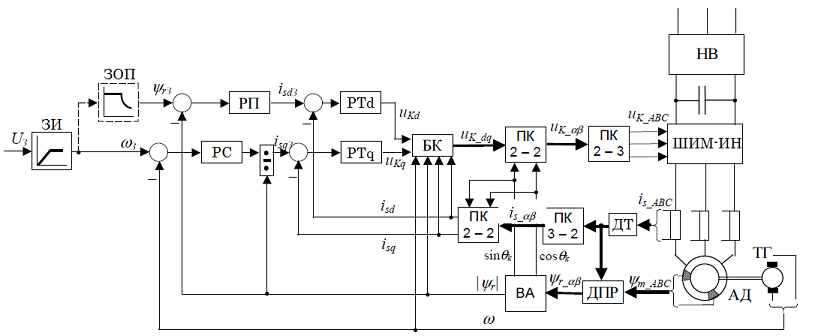
Figure 7 – functional diagram of the system of vector management of blood pressure
3.3 Permanent magnet synchronous motor vector control
Modern permanent magnet synchronous motors (PSM, Permanent Magnet Synchronous Machine (PMSM)), which operate in the sinusoidal form of phase currents, also called valve motors, are characterized by a high density of airflow in the air, a large ratio between the electromagnetic moment and the inertia moment , small torque pulsations in the whole range of speed control, up to low speeds, which is especially important for positional drives, as well as the ability to control the torque with a stationary engine. They have a high power factor and compact design. Valve engines are available at nominal moments up to tens of newtons per meter and are used in various mechanisms that require high static and dynamic drive characteristics [ 1 ]
In this paper, we will consider the SDPM vector control system in the coordinate system d, q .
Figure 8 shows the functional diagram of the vector control system of a synchronous motor with permanent magnets.
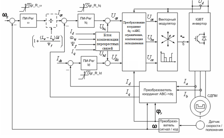
Figure 9 – Functional diagram of the vector control system of a permanent magnet synchronous motor
4 Output
Machine tools with numerical control are widely used in industry and require precise positioning and speed, as well as high-quality transients. To machine tools with numerical control put forward the main requirement – to produce high-quality products. These aspects require further study of the operation of electric drives and their control systems, modeling and analysis of existing systems.
List of sources
- Соколовский Г.Г. Электроприводы переменного тока с частотным регулированием : [учебник для студ. высш. учеб. заведений] / Георгий Георгиевич Соколовский. – М.: Издательский центр
Академия
, 2006. – 272 с. - Виноградов А.Б. Векторное управление электроприводами переменного тока / ГОУВПО
Ивановский государственный энергетический университет имени В.И. Ленина
.– Иваново, 2008.– 298 с. ISBN - Методичні вказівки до лабораторнихі практичних робіт з курсу
Моделювання електромеханічних систем
(для студентів спеціальності 7.0922.03Електромеханічні системи автоматизації і електропривод
). Розділ 2Моделювання систем електроприводу змінного струму
/ Укл.: О. І. Толочко, Г. С. Чекавський, О. В. Пісковатська – Донецьк: ДонНТУ, 2005. – 92 с. - SINAMICS S120 – Встраиваемые преобразователи частоты
- Числовое программное управление [Электронный ресурс]. Режим доступа: https://ru.wikipedia.org/wiki/ЧПУ
- Устройство и принцип работы двигателя на постоянных магнитах[Электронный ресурс]. Режим доступа: http://slarkenergy.ru/oborudovanie/engine/na-postoyannyx-magnitax.html
- Устройство и принцип работы двигателя на постоянных магнитах[Электронный ресурс]. Режим доступа: http://www.ets.ifmo.ru/usolzev/posobie1/vect_upr.htm#erste_teil