
Abstract
Содержание
- Introduction
- 1.Theme urgency
- 2.The purpose and objectives of the study, the planned results
- 3.Machine room – component of the trapping shop
- Conclusion
- References
Introduction
A large role in the workshop is played by the machine-condensation department. Several gas heaters are installed in the engine room. They are also called gas blowers. They are designed to extract gas from coke ovens and pass it through special equipment of the recovery plant and desulfurization plant, and then return the cleaned gas back to the coke workshop as fuel. If the engine room stops, that is, the gas blowers do not function, the coke ovens will not work and the coking process will stop. The machine-condensation department is considered one of the most difficult and responsible places in a manufacturing plant.
1. Relevance of the topic
The stable operation of the coke-chemical plant as a whole is largely determined by the reliable and optimal operation of the machine room of the chemical recovery plant. coking products, in particular, the equipment of the machine – condensing section. In the machine room is installed several gas blowers (gas blowers). They are designed to suck gas from coke ovens and create pressure for its supply through special equipment of the recovery plant and desulfurization plant up to before returning the purified gas to the coke oven for heating the furnaces. When an emergency stop of the blowers of the engine room, the hydraulic mode of coking is disturbed and The short operation of the coke ovens is possible only with open risers with emissions of all gas into the atmosphere, where it immediately ignites. Therefore, optimization the operation of the machine – condensing section is one of the most responsible tasks. This is especially true in connection with the increased requirements of environmental services.
2. The purpose and objectives of the study, the planned results
The aim of the work was to develop scientific principles for improving (modernizing) existing technologies and specialized equipment, improving the quality of products, creating technologies for the production of new types of finished products. For the result was carried out:
• study of the composition and physic &ndash chemical properties of the feedstock as one of the most important factors influencing the process and the quality of the result;
• mathematical modeling of gas separation processes in industrial plants, the development of technical solutions to improve work efficiency;
• improvement of technological processes and instrumentation, development of recommendations for optimizing process parameters and, on this basis, improving the quality of commercial products.
3. Machine room – component of the trapping shop
The complex of the coking plant’s coking plant, which it would be more correct to call the coke oven gas treatment unit
, is designed to divert coke oven gas from the furnaces, cooling it to release condensable resin,
water, extraction of ammonia from gas, pyridine bases, benzene hydrocarbons, gas purification from naphthalene, hydrogen sulphide and hydrogen cyanide and transfer of gas to consumers or a station to increase pressure.
The coke gas processing department is one of the most important technological units of the coke-chemical plant, without whose normal operation the operation of the coke shop and the entire production is generally impossible.
Fig. 1 – Variants of schemes (A, B, C) of coke oven gas treatment
(animation: 5 frames, 5 cycles of repetition, 65.3 kilobytes)
The sequence of processing of coke oven gas at different plants may vary. Figure 1 shows the various options for the processing of coke oven gas. Option B has the following advantages:
– ammoniacal serum cleaning, including a naphthalene cleaning unit, allows you to use your own absorbing agent and conduct subsequent treatment of gas that is free of aggressive and complicating agents;
- capturing ammonia in a circular ammonium - phosphate process allows simple anhydrous ammonia to be obtained using simple technology, without consuming extraneous reagents and providing for the complete destruction of ammonia;
– complex gas final cooling unit is eliminated, costs of heat and water are significantly reduced.
It is possible to partially use the solutions of variant B, for example, replacing ammonium sulfate production in variant A with the preparation of anhydrous ammonia. Naphthalene cleaning can also be provided for either during primary or final cooling. For all options characteristic is I process a large volume of poisonous and explosive gas saturated with water vapor at pressures slightly different from atmospheric (the vacuum in front of the supercharger is 4 5 kPa, and the excess pressure on the discharge side is 20 30 kPa). Mixtures of coke oven gas with air are explosive with coke oven gas content of 6 to 30% by volume. Therefore, all working gas equipment must be sealed, all gas pipelines, like all devices, must be equipped with reliably operating water traps and condensate drainers; Most of the equipment and gas pipelines are located outdoors. Given the significant temperature fluctuations during the year, it is necessary to equip the pipelines with a thermal compensation system and equip all hydraulic locks and traps with a heating system. The operation of the gas industry of the gas [1] treatment compartment is complicated by the presence of naphthalene vapor, naphthalene aerosols and tar in the gas. High volatility of naphthalene and its ability to form aerosols, as well as high temperature of its crystallization (80 ° С), contribute to its movement almost throughout the gas path and create the danger of the formation of naphthalene plugs in gas pipelines and other utilities. It is necessary to control the resistance of the apparatus and sections of gas pipelines, the level of liquid in the apparatus. Control of resistance and shutdown of the apparatus, group of apparatuses, pipeline section for revision, cleaning, steaming or flushing in case of exceeding the maximum permissible resistance – important condition for the normal operation of the gas treatment compartment.
The toxicity and explosiveness of coke oven gas makes it especially important to organize work when starting and stopping equipment, when disconnecting equipment or gas pipeline sections for repairs. Any inoperative apparatuses or sections of gas pipelines should be shut off with plugs for all communications without exception – gas, steam, oil, water, condensate, impulse instrumentation lines, etc., regardless of the presence of stop valves. The devices must be connected to the atmosphere, the state of the environment in them must be monitored. There are some general rules for the design and operation of gas and water management systems for the gas treatment department.
The location of the gas treatment unit should have a high building factor. This is important not only for better use of the land, but especially for reducing the length of communications. The use of short communications reduces capital and operating costs, heat losses and energy costs for transportation gases and liquids, increases reliability and reduces inertia of regulating devices. Reducing the length of communications is especially important when transporting crystallizing or evolving deposits of media. This applies, for example, to gas pipelines of coke-oven gas saturated with naphthalene. At the same time, it should be possible to access the main equipment, the ability to repair and install - dismantle the outdoor equipment by cranes or vehicles with a mounting tower.
To reduce energy consumption and increase the reliability of the coke oven unit and the separation of gas processing, the following conditions must be met: the shortest length of gas pipelines; reduction of local resistance due to the correct choice of configuration and location of knees, tees, etc .; minimum number of regulating devices (diaphragms, throttles, etc.).
The latter condition determines the emerging tendency to use for each supercharger its own independent gas flow: from the coke oven battery to the gas outlet from the processing system. This simplifies and reduces the number of regulating (distributing) devices. Where the gas flow is distributed in parallel operating devices (this applies in particular to gas refrigerators)
special measures have to be taken to maintain the same resistance of the apparatuses [2]: continuous washing of the annular space of primary gas refrigerators in order to prevent naphthalene deposition, washing of saturators, etc.
Coke oven gas treatment – the largest consumer of cooling water consumed for cooling gas in primary refrigerators, for final cooling of gas, for cooling streams of circulating solutions and condensation of vapors in the ammonia trapping, serocyan treatment, and benzene hydrocarbon trapping facilities.
The idea of ??the amount of heat removed gives the amount of water lost to evaporation in cooling towers, which is 0.42 in summer – 0.55 Nm 3 / t of coke, and in winter, decreasing to 0.30 &0.34 Nm 3 / t of coke, which amounts to 1.5% vol. on the amount of water circulating in the cycle of circulating water supply of the gas treatment section. In addition, 0.10 – 0.13 Nm 3 of water per 1 ton of coke is carried out in the form of splashes and another 0.05 Nm 3 / t
derived from the cycle of recycling water (the so-called flow water
) to prevent the accumulation of salt in the latter.
As a result, the circulating water supply system and cooling towers turn out to be an important element of the capture shop, and the quality of the main equipment operation, which depends significantly on the gas temperature and, depends on the right choice of design solutions. absorbents, the reliability of the equipment and, in particular, its corrosion. The fact is that on the territory of the coking plant there are a large number of objects that moisturize the atmosphere: cooling towers, towers of wet extinguishing with sludge septic tanks, aerotechnics of biochemical plants, "air", emitting water vapor and a pair of aggressive substances. Air humidification seriously increases the risk of equipment corrosion, which is aggravated by significant air dustiness. The location of the cooling towers near the air-humidifying apparatuses impairs their operation: humid air impairs the operation of the cooling towers, raising the temperature of the "wet thermometer" by several degrees and, accordingly, increasing the temperature of the cooled circulating water. A serious danger is the dust in the atmosphere of industrial enterprises. Large amounts of air passing through the cooling tower are freed from dust in it, the amount of which is significantly greater than the amount of salts and sludge applied with fresh water. The operation of the circulating water supply system to a great extent depends on the relative position of the cooling towers, the main installations of the trapping plant and the sources of dust generation. Their placement should be based on the "wind rose" and the free flow of fresh air.
The operation of cooling towers is influenced by the amount of overheating of circulating water in heat exchange equipment above 42 – 45 ° C, with the beginning of the decomposition of calcium bicarbonate:
As a result, the aggressiveness of water vapor increases and at the same time the deposition of fine, poorly soluble calcium carbonate on metal structures and cooling tower packing begins. In some factories there have been cases of nozzle collapse from &ldash; for increasing its mass under the influence of sediments. The experience of a number of industries shows that stable non-boiling the operation mode of cooling towers and heat exchanging equipment is provided when the temperature difference when heating the circulating water is not more than 10 ° C. This requires an increase in the frequency of circulation in the system, an increase in energy consumption, but ensures more stable and reliable operation of all equipment, reduces equipment wear, reduces the number of repairs and stops. For cooling of circulating water in the coking industry, cooling towers of three main types are used: tower, fan pressure and fan exhaust, their device is shown in Fig.2. In recent decades, exhaust cooling towers have been built predominantly. Tower cooling towers are mainly used in old plants.
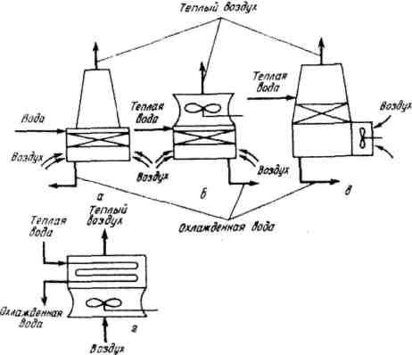
Pic. 2 – Tower, fan pressure and fan exhaust cooling towers
Conclusion
Qualitative synthesis of digital systems, and Moore automata in particular, is one of the areas of logic design,
and is not only theoretical research but also of practical interest. Development of optimal digital devices opens the way for
more efficient use of capacity basis the implementation of compaction
of projects, reduce material costs.
Master's work is devoted to actual scientific problem of combining the basic methods of minimizing the instrumental Moore automata. In the trials carried out:
- The structure of a unified process for the synthesis of Moore automata and defines the functions of its components.
- Based on analysis of the literature highlights the main algorithms that can be used in the proposed approach to the unification of the synthesis of Moore automata.
- A number of experiments on the use of a unified process for the synthesis of Moore automata, analyzed the results.
- The possibilities of integrated automation of the developed approach to the unification of the synthesis of Moore automata are estimated requirements for the software by searching for functionally similar software synthesis of sequential logic circuits.
Further studies focused on the following aspects:
- Qualitative improvement of the proposed approach to the unification of the synthesis of Moore automata, its complement and expand.
- Delimitation of the effectiveness of different variants of the basic stages of a unified process for the synthesis of Moore automata.
- Adaptation of known methods of constructing the logic of Moore automata to the base FPGA.
- Develop cross-platform functionality and computer-aided design of Moore automata (CAD) software that implements the proposed unified process synthesis.
This master's work is not completed yet. Final completion: December 2011. The full text of the work and materials on the topic can be obtained from the author or his head after this date.
References
- Постійний технологічний регламент № 8: виробництво сірчаної кислоти контактним методом за схемою ДК – ДА введено в дію директором Макіївського Державного хімічного заводу № 8 – 1997. – 62 с.
- Инструкция по эксплуатации пылеулавливающей установки беспылевой выдачи кокса батареи № 1 коксового цеха ОАО «ЯКХЗ»-2007. – 49
Основные правила техники безопасности при прохождении производственной практики
/Методические указания кафедры МАХП, ДонНТУ- ПАО
Ясиновский коксохимический завод
: Главная страница.- [Электронный ресурс] Украина. Донецк.-2013.< - Гомельский А.З. Аппаратчики коксохимеческих производств. 2 издание. Харьков-Москва.Металлургиздат, 1953. 384 с
- Дмитриев М.М., Абуховский Е.М. Краткий справочник коксохимика. Москва: Металлургиздат, 1960, 253с.
- Лейбович Р.Е., Яковлева Е.И., Филатов А.Б. Технология коксохимеческого производства. 3 издание, Перераб. и доп.-М.:Металлургия, 1982- 360с.