
Summary of the final work
Content
- Introduction
- Main content
- The process of removing the material of the workpiece grains HK
- Section cut parameters
- Conclusions
- List of sources
Introduction
The growing needs of various branches of engineering in new materials with new properties contribute to a wider use of technical ceramics (TC). Products from the TC can be used in almost all industries where metal products have already exhausted their capabilities or are used to the limit of their capabilities. For this reason, recently, ceramic products are increasingly replacing metal and polymetallic products.
To ensure the high-quality and accurate manufacturing of ceramic products, most manufacturers use diamond grinding and polishing as final machining, since these types of processing are cheaper than laser and ultrasonic, do not require the introduction of new expensive equipment, and personnel training.
Due to the high hardness of the TC, diamond grinding wheels (CC), when it is machined, lose their cutting properties [1, 2]. When grinding TC, the parameters of the working surface of the circle (PKK) change, cutting forces increase, processing performance decreases, micro- and macrocracks can form on the surface of the products, deviations in the shape of the part increase, accuracy decreases, etc., which adversely affects the performance products in particular to reduce their strength [3]. The wear of the grains of the grinding wheels (figure 1) depends on the cutting force on them, which is determined, first of all, by the section of the material cut-off on them. In the following, we will consider a method for calculating the average cross-section of the material cut-off on the grain for a flat plunge grinding scheme.
Fig. 1. Animated example of the process of wear of diamond grains (5 pictures, 5 frames, 130 kb)
The main content of the work.
The location of the grains on the working surface of the circle can be considered as a non-stationary field with a Poisson distribution. The working surface of the circle is uniform in different directions. In this connection, the number of grains per unit of the working surface of the circle n3 is assumed to be constant for its entire depth δu from the most prominent grain to the bundle. The distribution of the vertices of the grains along the height u of the working surface of the circle is uneven and is adequately described by the Weibull distribution [4].
For a flat mortise grinding scheme (Fig. 2), the current maximum depth of penetration of grain into the processed material, located at the working surface depth u and its angular φi position in the cutting zone, is determined by the dependence:
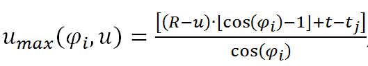
where R – grinding wheel radius, mm; u is the coordinate of the location of the top of the grain from the most prominent of the grain bundle on the PKK, mm; φ i — the current angular position of the grain on the surface of the circle in the working area, glad; t is the depth of grinding, mm; t j is the distance from the cutting surface to the considered angular position φi, mm.
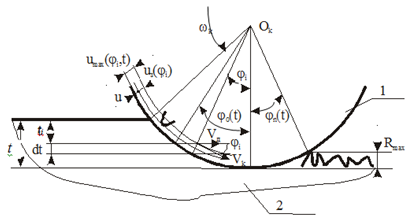
Fig. 2. Flat grinding scheme with periphery of a circle 1 – grinding wheel, 2 – workpiece
The dependence obtained allows us to take into account the variable conditions of the work of the grains, taking into account their differences in height, both within the PKK and along the generatrix of the circle.
To analyze the machining conditions in the case of flat grinding with the periphery and end of a circle, it is convenient to determine the zone of contact of the workpiece with the circle of entry angles (φo) and output φn) in her grains (Fig. 1). Then by simple calculations we get:
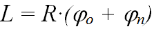
where L ‐ contact arc length, mm.
For flat grinding by the periphery of the circle, the total width of the grains passing through the section of the workpiece is determined by the dependencies:
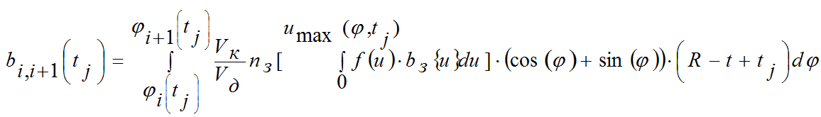
where b – total grain width, mm; V k – lap speed, m/s; Vd – part speed, m/s; n h – the number of grains per unit of the working surface of the circle; f (u) ‐ area of cut, mm2; bh – width of one grain, mm; t ‐ depth of cut, mm; t j ‐ depth of the location of a single site, mm.
The obtained value b i, i + 1 (t j) characterizes the vector field of the grinding wheel, determines its ability to remove the material of the stock of the workpiece.
The process of removing the material of the workpiece grains HK
The flow of workpiece material is a vector quantity that is variable in time and space. The direction of movement is determined uniquely by the velocity vector for each point in space. The scalar characteristic of the material field is determined by the probability of material removal P (Ai, tj):
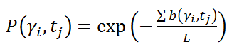
where Sb (γi, tj) is the total width of all single grains that have passed through the base portion of Lb on the level of the radial coordinate tj, measured from the surface of the workpiece, with the angular arrangement of the section γi.
Since the total width of all the scratches when the angular position of the section changes changes, the field is variable in the work area.
Slice Section Settings
They relate to one of the most important characteristics of the cutting process during grinding, which determine its force, heat and many other aspects. Cutting forces on diamond grains cause wear and destruction of the latter, which leads to a change in the distribution of the tops of the grains on the working surface of the circle. As a result, there is a redistribution of the removed material of the allowance between the active (cutting) grains of the circle and the average cross sections of the cut on the grains change. The irregularity of the position and orientation of the grains on the working surface of the circle necessitate the use of statistical characteristics.
The sectional area of a slice on a single grain will be determined according to the scheme shown in Fig.3. The probability of non-removal of the stock material depends on the location of the site on the angle γi and the depth tj in the cutting zone. The projection of the elementary part of the workpiece with the height dt onto the grain du depends on the angle of the meeting of the platform with the grain (γi+φi) and is defined as: du=cos(γi+φi)dt. The sectional area of the slice on the grain is determined by the integral:

where C b and m is the proportionality coefficient and the exponent, depending on the grain size and grain grade.
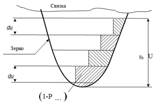
Fig. 3. Diagram of the distribution of the section of the slice along the height of the working part of the grain
The total area of the material f σ removed by grains in the radial section of the workpiece γ for a planar grinding scheme, determined by summing the sections of the cut across the entire working area:

The distribution of the total sections of the section of the material removed in the working area with a circle of unit width for round external plunge grinding is calculated from relation (6). The largest total cross sections of the cut-off material allowance occur at the beginning of the working area at the surface of the workpiece. Then they are gradually reduced to the treated surface. This agrees well with well-known facts.
For the analysis of the working conditions of grains, the greatest interest is the value of the average cross sections of sections of the processed material on the grains. The average section cut on the grain f3 is determined by the dependencies:
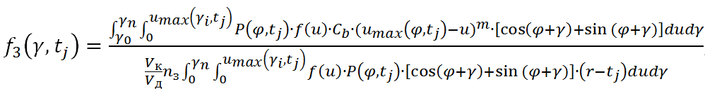
where γ – angle that sets the position of the site under investigation, glad.
Conclusions
Establishing the basic laws that relate the geometrical and physical parameters of the topography of the cutting surface with the parameters of the cutting process and the quality criteria of the surface to be processed makes it possible to proceed to standardization and control of the main characteristics of the working surface circle. Determining the most important characteristics of the cutting process, in particular, the average cross section of the slice, can significantly improve the quality of the surface layer of the workpiece, which ultimately leads to improved product quality without increasing the cost of machining.
List of sources
- Пташников, В. С. Физическая и нормативная твердость абразивных инструментов из высокотвердых и сверхтвердых материалов. Часть 1. Физическая твердость абразивных инструментов // Сверхтв. материалы. – 2004. – №4. – С. 75-88.
- Гусев, В. В. Закономерности изменения состояния рабочей поверхности алмазного круга при шлифовании керамики/ В.В. Гусев, А.Л. Медведев, В.В. Савельев //Наукові праці Донецького національного технічного університету. Серія «Машинобудування і машинознавство». – Донецьк: ДонНТУ. – 2007. – Вип. №4 (124). – С.21-30.
- Гусев, В. В. Влияние состояния алмазного круга на качество поверхностного слоя изделий из керамики // Надійність інструменту та оптимізація технологічних систем. Збірник наукових праць. - Краматорськ: ДДМА. – 2002.– Вип. №12. – С.234-241.
- Воробьев, А. А., Гусев, В. В. Описание процесса износа алмазных зерен при шлифовании керамики// Инженер. – 2017. – Вып. №4. – С.21-24.
- Пташников, В. С. Физическая и нормативная твердость абразивных инструментов из высокотвердых и сверхтвердых материалов. Часть 2. Физическая твердость абразивных инструментов // Сверхтв. материалы. – 2004. – №5. – С. 74-83.
- Гаршин А. П., Гропянов В. М., Лагунов Ю. В. Абразивные материалы. – Л.: Машиностроение, 1983. – 231 с.
- Справочник технолога-машиностроителя: В 2 т. - 4-е изд. Перераб. И топ. – Т.2 / Под. Ред. А. Г. Косиловой и Р. К. Мещерякова. – М.: Машиностроение, 1985. – 496 с.