
Abstract
Content
- Introduction
- 1. Sludge recycling process as a control object
- 2. Purpose and objectives of the study
- 3. Review and analysis of known solutions for the control and management systems of the activated sludge recirculation pump station
- 4. Justification of the accepted direction of solving the problem
- Findings
- List of sources
Introduction
Sludge treatment facilities are a complex complex of engineering structures interconnected by the technological process of wastewater treatment. Pumping station recirculation of activated sludge – is a group of a group of pumping units that perform a common task.
The main purpose of the pumping station of recirculation of activated sludge is continuous pumping of activated sludge from radial sedimentation tanks to regenerators of aeration tanks, where the regeneration of the active properties of sludge occurs, that is, the resumption of its oxidizing ability. Excess sludge thus selected and supplied through the pressure pipe in preparatory and receiver tanks.
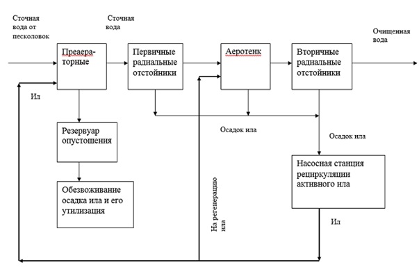
Figure 1 – Scheme of movement of sediment when processed.
Like any other important system, it requires economically sound technical solutions at the stages of its design and automation.
1. Sludge recycling process as a control object
Most treatment plants nowadays use outdated equipment, which affects not only the reliability of equipment and systems, but also the technological processes of the entire enterprise. The exception did not become and pumping stations of recirculation of activated sludge, working in the normal mode, and do not have the means of regulating the processes of their work.
The electric drive is the power basis of modern production and, in turn, among the industrial electric drives are dominated by electric drives with asynchronous squirrel-cage motors that consume up to 50% of the energy consumed by the electric drive. These actuators, due to their simplicity and relatively low cost, are widely used in various mechanisms. Their disadvantages are also well known — a heavy start with direct connection to the network, accompanied by six–seven-fold currents, and, as a result, low operational reliability, difficulty in speed control. The excessive level of electricity consumption is a consequence of the low efficiency of pumping units and stations as a whole. With the introduction of an automatic process control system into production, the form and nature of work is qualitatively changing, safety, skills and knowledge of workers are increased, the line between physical and mental work is blurred.
In the vast majority of cases, the electric drives of these mechanisms are unregulated, which does not allow to provide a mode of rational energy consumption and consumption when changing technological needs within a wide range. Selected on the basis of maximum performance, these mechanisms work much of the time with less performance, which is determined by the change in demand at different times. In systems without automatic control of activated sludge recirculation pumps, it is completely impossible to influence or regulate the sludge pumping process in any way. After the introduction of ACS elements, it is possible to adjust the performance of the pump, taking into account the unstable density of the pumped sludge, thereby following the specified parameters of operation and technological processes.
2. Purpose and objectives of the study
The purpose of the pumping station control system is to improve the efficiency of the pumping station, which will extend the service life of the process equipment, improve reliability and safety, as well as reduce operating costs for the process of pumping activated sludge and reduce energy costs. The main functions to be performed by the automatic control system of the pumping station:
1) control functions:
— smooth start and stop of the pump;
— automatic stop of pumps in case of failure of their operation or according to the process of pumping of activated sludge;
2) automatic control of the main technological parameters of the pumping station-supply, pressure.
3) protection function:
— to protect the pipeline from overpressure;
— protection against cavitation phenomena;
— protection against water hammer.
4) information:
— collect information from sensors and transmit it to the control controller;
— system malfunction alarm;
— communication master controller with the control point to receive and transmit data.
3.Review and analysis of known solutions for the control and management systems of the activated sludge recirculation pump station
one of the main ways to automate pumping stations is to use a Frequency Converter (FC), shown in figure 2.
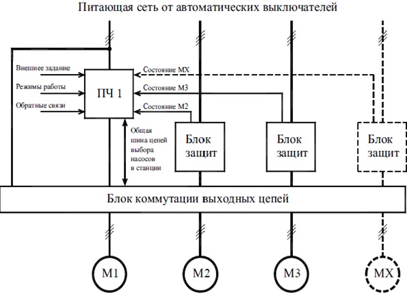
Figure 2 – Functional diagram of the pump station control system with one Frequency Converter.
The main advantage of this scheme is the ease of implementation at the lowest cost and the ability to operate the station in automatic mode with direct starts on the open valve. The main drawback of this system is less reliability compared to other options, due to the use of only one control element. The most popular and budget configuration of systems resembles the previous scheme with the addition of thyristor devices for smooth start and stop of electric motors of subordinate pumps. This ensures their shock-free start and stop on the open piping system. A functional diagram of this configuration is shown in figure 2.1.
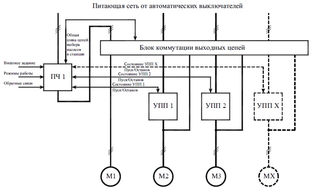
Figure 2.1 – Functional diagram of the pump station control system with one Frequency Converter and soft starters.
It is necessary to allocate one more variant of the decision when output circuits of the frequency Converter can be connected to the electric motor of each subordinate pump through additional starters. This allows you to switch the frequency drive to any of the electric motors of the station, which ensures uninterrupted operation of the system in case of failure of any pump, and also equalizes their loading time with an increase in the resource of the entire scheme. Among the disadvantages of this solution is the increase in the number of start-up equipment. Starting with an electric motor power of more than 90 kW, this is not justified and leads to an increase in maintenance and operation costs. Therefore, with a single power of more than 110 kW, it is advisable to configure the station control system, when each motor is installed with its own frequency Converter. The functional diagram of such a pump station control system is shown in figure 2.2.
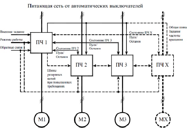
Figure 2.2 – Functional diagram of the pump station control system with slave frequency converters.
The effect of one speed of rotation of all pumps can have an additional up to 10...12% of the total contribution to energy saving. The reason is that there are no pressure losses in the outlet manifold due to the different flow rates of the pumped medium from the pumps in the group. At the same time, there is a significant reduction in the cost of maintenance and operation of the station management system itself. It is possible to provide the choice of any pump as the main one without cumbersome switching circuits of output circuits and in emergency situations on the output circuits of the frequency Converter to leave the control circuit in operation on other pumps. Selection of frequencies at which the smooth start, stop and speed control of the electric motors of the subordinate pumps is performed in the zones of maximum pump efficiency, taking into account the permissible number of starts per hour of the electric motors and the permissible pressure change in the pipeline system.
4.Justification of the accepted direction of solving the problem
for lower power consumption, a control method is used that focuses not only on maintaining the set pressure, but also to control the efficiency of the pumping station. As a criterion for the efficiency of the pumping station is used its hydraulic efficiency, which is determined by the formula:
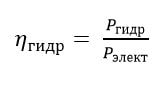
where P Hydra hydraulic power developed by the pumping station, i.e. the power transmitted by the liquid pump;
Pelect & ndash; total electrical power consumed by drives of regulated pumping stations
units and drives of pumps operating from the network.
Electrical power is a measured parameter, hydraulic (net power) is determined by the formula:
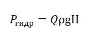
where Q & ndash; pump station flow, m3 / s;
H – full pump head, m.
The Full pressure of the pump:
where Z – is the height of the center of the pipeline cross section above the reference plane;
the since the pipeline section at the inlet and outlet of the pump unit is the same, the dynamic component of the head is neglected.
the change in pressure and power when adjusting the impeller speed for centrifugal pump units is described by the equations,
given below. Pressure characteristic of the pump:
where A2, B2, C2 & ndash; coefficients determined by the characteristics of the pumping unit;
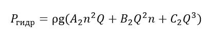
the the useful capacity of the pump unit is Determined by substituting (4) and (2):
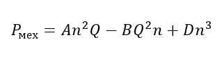
At the same time, the mechanical power consumed by the pump when the rotation speed changes is significantly affected by the circulating
and mechanical losses in the pump. In General, the equation of mechanical power:
where a, B, D – coefficients determined by the characteristics of the pump unit.
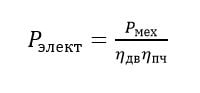
for an adjustable pump, the energy consumption will be determined by the formula:
where η DV, ηif – efficiency of motor and frequency Converter.
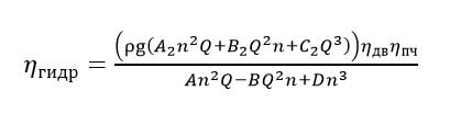
Substituting equations (5) – (7) into (1), we obtain an analytical dependence of the pump efficiency change on the speed:
To avoid inefficient operation of the regulated pumping units, it is proposed to determine the instantaneous efficiency of each of them,
and then include an additional pump unit in the case of reduced efficiency below a predetermined threshold. Instant efficiency is evaluated,
based on the power consumption of each of the pumps, and from it develop the pressure and flow rate. The expense is estimated,
based on the passport pressure characteristics of the pump and the current speed of its impeller.
The pumping station for recirculation of activated sludge is considered as a control object. Its features and some characteristics were listed.
The activated sludge recirculation Pumping station was considered as a controlled facility. The use of a frequency Converter in order to reduce energy costs is considered.
Also, various control schemes were considered and their advantages and disadvantages were identified. According to the above information, goals were set
and the tasks of automation of development, as well as user requirements for the control system were defined.
The choice of the automation solution direction was explained.
ρ & ndash; liquid density kg / m3< / sup> ;
g –gravity acceleration, m / s2< / sup> < / p>
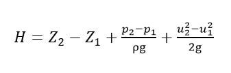
R & ndash; the gauge pressure is assigned to the center of the cross section;
the
u – the average axial velocity, determined by the ratio of volumetric flow to the cross sectional area of the pipe.
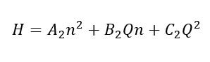
n – frequency of rotation of the impeller;
the
Q – consumption developed by the pump Assembly.
Findings
List of sources