
Abstract
Contents
1. Introduction
Modern lifting equipment is one of the most important structures mine complex. This is a complex electromechanical mechanism, consisting of separate elements, performing various functions. From The normal operation of this installation is uninterrupted and productive the work of the entire mine, because the lifting installation is the main link an element between the surface and underground part of the mine. In the event of an exit the operation of the whole enterprise stops.
One of the factors influencing the operation of the installation is the thermal balance bearing units.
At most mines, the temperature of the bearing units is not controlled, or controlled by equipment executed on outdated elemental base and does not correspond to the current level and norms. This leads to an increase in the number of installation downtime and k additional losses. Therefore, the development of control equipment the bearing units of the mine lifting installation, which will be to reduce the number of installation downtime, is relevant.
2. Objective
Thus, the aim of the work is to increase the efficiency the work of mine lifting installation by improving equipment control the temperature of the bearing units.
3. Automation object and its features
Main skip lift - the main link between underground part of the mine and its surface. It is designed for lifting equipment, materials, minerals and rock. According to Figure 1, the speed of the vessel is controlled tachogenerator BV1 and BV2. The tacho BV1 receives rotation from lifting motors 1, and BV2 - from the retarder device. From tachogenerators emf arrives at the appropriate relay restrictions speed K1 or K2.
Using magnetoelastic inductive sensors 2 and 4, which installed under the shells of the pile driving pulleys 3, The skip hangs in the trunk is controlled.
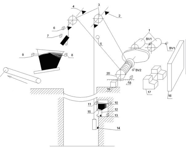
Figure 1 - Technological scheme of automated skip hoisting installation
Skip re-skid protection by contactless inductive sensors 5 and 6 on a scraper and limit switches on control panel 17 in the depth gauge block.
Skip approach to the place of unloading on the scraper and loading in the barrel controlled by explosion proof magnetic switches 7 (unloading) and 14 (loading).
The level of the lower and upper bins is controlled by mines. explosion-proof gamma relays. The flow of gamma rays from sources 8 (upper bunker) and 10 (lower bunker) passes through a controlled Wednesday and recorded sensors 9 and 11.
When dosing a skip using weight, the dose of coal is weighed. force measuring sensor 12 (magnetoelastic or strain gauge), the signal from which is received by the electronic unit 13. 15 - executive loading device mechanism, 16 - lifting control scheme machine, 20 - bearing temperature sensors.
Modes of operation of skip hoist installation
On the main skip rise provides the opportunity the implementation of two modes of operation: with full speed and reduced.
Full-speed operation is performed during descent and ascent. equipment, delivery of cargo from horizons.
The mode of operation with reduced speed is carried out during revision the barrel, the descent of explosive substances and other auxiliary operations.
Installation control method is automatic. With this method lifting cycle is carried out according to a given tachogram without intervention person The remote control is located on the receiver. plot in the top of the building.
Figure 2 shows a tachogram of movement of skips installation. Six-period tachogram with rectilinear change speeds in unspecified periods.
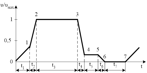
Figure 2 - Tachogram of movement of skips of a lifting installation
During the period of the vessel reaching out to the place of unloading, motor force on the rim of the drum during the entire period. When descending chart matters moving effort below zero.
According to Figure 2, movement is carried out at station 0-1 lifting vessel in discharge curves.
At section 2-3, the lifting vessels move at maximum speed. Section 4-5 corresponds to the movement of the skip in the discharge curves. At station 5-6, a final shutdown process takes place. Plot 6-7 corresponds to a pause between two periods of recovery.
In Figure 3: t0 is the acceleration period when the skip moves in curves, t1 is the period of normal acceleration after the skip leaves the curves, t2 - the period of movement with a maximum speed t3 - the period of normal deceleration, tп - the period of movement of the skip with the speed of doping, tс - the time of locking the machine.
The purpose of the design is to increase the efficiency of the mine lifting installation by developing an automatic protection unit bearings overheating.
Requirements for the automation system of the lifting installation:
- control of loading and unloading equipment as technological equipment installation;
- ensuring the software execution of the tachogram regardless load changes within specified limits;
- ensuring the safety of the installation and alarm modes work, and the reasons for deviations from the specified mode;
- availability of protections and interlocks for monitoring individual faults items of equipment;
- communication with the operator and the possibility of setting the settings and implementation of visual control over the work;
- temperature control bearing units on the installation.
Tasks that are solved:
- develop new equipment for temperature control of bearings;
- to expand the functions of the new equipment in comparison with the old.
Technical requirements for temperature control equipment:
- controlled temperature - 70 ° C;
- permissible deviation of the response temperature from the controlled one - 5 ° С;
- inertia - no more than 20 s; number of controlled nodes - not less than 6; nominal resistance at 0 ° C = 100 Ohm;
- conversion limits - 0 to 90 ° С
System overloads and bearing failure may cause to stop lifting for a significant period of time that in its the queue will lead to the shutdown of the entire mine and additional losses.
To assess the dynamic properties of the control object developed mathematical model of bearing heating based on the heat equation balance. The main parameters of the equations of the model are the coefficient cooling and bearing weight, design, heat capacity, coefficient friction.
The temperature of the bearing in steady state depends on the load, rotational speed and thermal conductivity characteristics of the machine. Differential equation describing temperature change bearing as a function of time is:
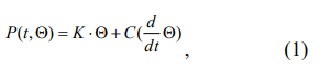
where K is the cooling coefficient, W / ° C; & theta; - bearing heating temperature, ° С; C is the bearing heat capacity, (W * h / kg * deg); t is the simulation time, s.
The differential equation in the form of Cauchy has the form:
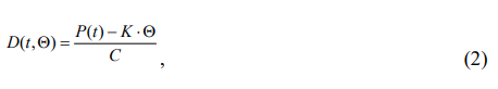
where P (t) is the change in friction power in the bearing as a function of time. Under normal conditions, the heating process of the bearing is inertial and not undergoes sharp temperature changes, as can be seen in Fig.1. Schedule changes in friction torque (Fig. 1) is determined by the expression:
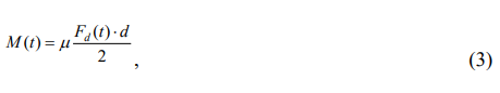
Where η - coefficient of friction; Fd (t) is the change in the diametral load on the bearing as a function of time, N; d - diameter of the bearing, m.
We will develop a model of the process of heating the bearings of the lifting installation on based on the use of physical laws that describe behaviors and state of the object. The heat balance in the bearing is set by friction torque M (N * m), friction power Del Ptr (W), which depends on friction forces, causing the heating of the entire bearing, and heat, which stood out in this, W (j), because the occurrence of significant The temperature difference is a consequence of increased friction in the bearing.
The friction power depends on the load on the bearing, namely the frequency bearing rotation and radial load. Also on heat balance the bearing is significantly influenced by its design, namely its the diameter, height and width of the shell that make up the outer cooling surface through which heat exchange takes place between the bearing and the external environment. It is impossible not to take into account the heat capacity material of which the bearing is made. Heat capacity depends on type of steel bearing and its mass. considered standard bearing for skip hoisting installation 2Ts-5 * 2.4 type 3003752. V the result of the simulation overheating of the bearing unit were obtained The following dependencies (Figure 3-5).
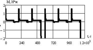
Figure 3 - Graph of friction torque in the bearing from the operating time of the lifting unit
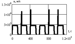
Figure 4 - Graph of the rotational speed of the bearing from the time of the lifting
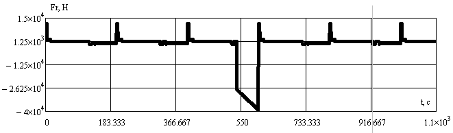
Figure 5 - Graph of the radial load on the bearing from the time of the lift
If there is not enough lubrication, the temperature rises sharply, as can be seen in Figure 6.
According to the results of mathematical modeling of the heating process bearing skip lifting installation, you can do the following findings. During normal operation of the lifting installation (without overload and good bearing) bearing temperature ranges from 35- 40 ° C, which corresponds to the PB during lifting operation. However, system overload and irregularity in the bearing (mechanical damage, pollution lubricants, and the like) cause a rise in the temperature of the bearing and the impossibility of its subsequent use until the temperature is again set in the normal range.
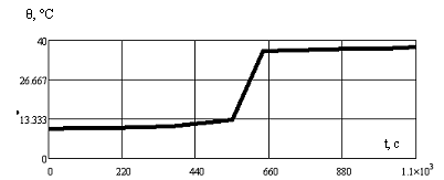
Figure 6 - The graph of the heating process as a function of time
Thus, the results show the need control the temperature of the bearings of the lifting installation since when the bearing will fail completely, the lifting operation will stop at a large length of time, and this will lead to the cessation of work of the entire mine and to additional losses (increased downtime, costs, replacement old bearing on a new one). Bearing temperature control avoids bearing replacement, reducing downtime and reduce costs.
The developed model allows to estimate the rate of temperature change. bearing and determine the settings for the prediction of overheating. An analysis of the literature [1] shows that for automation skip hoist installation is the most suitable system ZDKR.
The advantages include: the universality of the system - constant situation monitoring and provision of conditions for timely take precautionary measures to ensure safe work (registration, storage, automated reproduction historical information about the operation of the installation for the necessary temporary interval).
The disadvantages include the high cost of components system.
The purpose of this work is to modernize and introduce developed automatic temperature control unit bearing unit skip hoisting installation in this equipment. The block diagram of the device being developed is shown in Figure 7. The work of the structural scheme is as follows. Sensor Signals temperature TD 1..6 served on the bridge circuit, pass through operational amplifier, matching unit and input microcontroller. If the temperature exceeds 70 ° C - the microcontroller will issue a command to stop the lift installation. This includes sound alarm and display device. In the case of a gradual increasing temperature and exceeding the threshold of 60 ° C microcontroller will give a warning signal to the computer operator and turn on the device appropriate indication.
Figure 7 - Block diagram of the device controlling the thermal regime (animation: 3 frames, delay 150 ms, 35.5 kilobytes)
The given structural diagram consists of the following blocks: TD1..TD6 – temperature sensors; OU - operational amplifier; BEAD block coordination; MK – microcontroller; Power supply unit; UI – device indications; C – LEDs; CCB-block matching output signals.
Findings
As a result of the work performed, the level of automation and reliability skip hoist installation.
The advantages of the development should include:
- the ability to control the temperature gradient of the bearing units installation;
- the ability to adjust the threshold of the control equipment;
- the use of modern elemental base;
- low installation and maintenance costs.
This unit, being an integral part of a large system, can used both separately and as part of control equipment skip lifting installation.
At the time of writing this essay the master's work is not yet completed. Final Completion: June 2019. Full text of the work and materials on the topic can be obtained from the author or his manager after the specified date.
List of sources
- Бежок В. Р., Дворников В. И., Манец И. Г., Пристром В. А. Шахтный подъем: Научно–производственное издание / В. Р. Бежок и другие. Шахтный подъем: Научно–производственное издание. – Донецк:ООО «Юго–Восток,Лтд», 2007. – 624 с.
- Батицкий В. А., Куроедов В. И., Рыжков А. А. Автоматизация производственных процессов в АСУП в горной промышленности: учебник для техникумов. / В. А. Батицкий и другие. Автоматизация производственных процессов в АСУП в горной промышленности: учебник для техникумов – М.:Недра,1981.– 320 с.
- Дворников В. И., Къерцелин Е. Р., Трибухин В. А., Савенко Э. С. Динамические жесткости канатов шахтных подъемных установок / В. И. Дворников, Е. Р. Къерцелин, В. А. Трибухин, Э. С. Савенко // Стальные канаты. – Одесса, 2003. – Вып. 3.
- Шахтный подъем: Научно–производственное издание / В. Р. Бежок, В. И. Дворников, И. Г. Манец, В. А. Пристром; общ. ред. Б. А. Грядущий, В. А. Корсун. – Донецк : ООО «Юго-Восток Лтд», 2007. – 624 с.
- Степанов А. Г. Динамика шахтных подъёмных установок / Анатолий Григорьевич Степанов. – Пермь : УрО РАН, 1994. – 263 с.
- Степанов А. Г. Динамика машин / А. Г. Степанов. – Екатеринбург: Российская академия наук, 1999. – 392 с.
- Степанов А. Г., Корняков М. В. Динамика машин : монография. 2–е изд., испр. и доп. / А. Г. Степанов, М. В. Корняков. – Иркутск : Изд-во ИрГТУ, 2014. – 412 с.
- Степанов А. Г. Динамические процессы при скольжении канатов по футеровке барабана многоканатной подъемной установки / А. Г. Степанов // Горное оборудование и электромеханика. № 6, 2010. – C. 24-35.
- Колосов Л. В., Потураев В. Н., Червоненко А. Г., Безпалько В. В., Завозин Л. Ф. Вертикальный транспорт на горных предприятиях / Л. В. Колосов, В. Н. Потураев , А. Г. Червоненко, В. В. Безпалько, Л. Ф. Завозин. – М.: Недра, 1975. – 350с.