
Summary of the final work
Content
- Introduction
- 1. Relevance of the topic
- 2. Goal and tasks
- 3. Overview of approaches to planning the trajectory of movement of autonomous moving objects
- 3.1 Device neuro-fuzzy networks
- 3.2 Genetic algorithm
- 3.3 Potential Fields
- 4. Fuzzy logic method
- 5. Types and analysis of distance measurement sensors
- 5.1 IR distance sensor
- 5.2 Laser distance sensors
- 5.3 Ultrasonic distance sensors
- 6. Development of the block diagram of the device
- 6.1 Rationale for temperature dependence
- 6.2 Device block diagram
- findings
- Source list
Introduction
Robots are automatic systems designed to reproduce motor and intellectual functions of a person. From traditional machines are more versatile and adaptable to perform various tasks, including in a changing environment. Currently, robotics has become a developed industry: thousands of robots are working at various enterprises of the world, underwater manipulators have become an indispensable accessory of underwater research and rescue vehicles, space exploration relies on the widespread use of robots with different levels of intelligence. Special attention is paid to the automation of heavy, harmful, tedious and monotonous work in various industries with the help of robotic manipulators. Modern robotic systems are a set of the latest achievements of science and technology, and their versatility allows them to be used for a wide variety of tasks. One of the most important classes of robots for General purposes are mobile robots.
The mobile robot can carry out its activities both under the control of the human operator and autonomously. Giving a mobile robot autonomy requires solving a number of technically complex problems in the first place, of which is the planning of the trajectory. For an Autonomous universal robot, the problems of orientation and movement in the surrounding space are among the key ones. The robot should not imitate intelligent behavior, but really be intelligent. He should be aware-where he is, what are the features of this place and how from point "A", if necessary, you can get to point "B" in the shortest time or covering the minimum distance.
the presence of an advanced orientation system will allow the robot to plan its actions to move in space, calculate the optimal route, collect and use information about the obstacles surrounding the area, which ultimately will allow it to perform a useful functional load.
1. Relevance of the topic
currently, there are many systems including distance sensors, as well as other "sense organs" of Autonomous systems. However, some situations do not require a complex system, which could for example remember the location of objects, or GPS orientation. It is in these cases that the budget system consisting of a minimum of hardware is best suited.
in order to better immerse yourself in the subject area and come up with a good (fast and accurate) algorithm for identifying your position in space for a robot with one sensor, you must try to see the world through his eyes. This world is very specific. It can be represented as:
– Robot with contact sensor-man in a dark room with his hands tied (no hands). He goes until he hits the wall. Can follow along obstacles, periodically hitting on him.
– a Robot with a short-range distance sensor-a man in a dark room with his hands untied. He can move without encountering obstacles and learn about the nature of the obstacles around him at arm's length.
– a Robot with a long-range distance sensor-a man in a dark room with a flashlight (laser pointer). It can estimate the distance to opposite walls while staying in place.
Based on the above, it can be concluded that the organization of an Autonomous robotic system requires actuators, a microprocessor device and a distance sensor (sonar), as it fully meets all the conditions of Autonomous movement, due to the detection of obstacles at the required distance.
2. Purpose and objectives
the Aim is to develop an electronic device for measuring the distance to obstacles of moving objects.
the Purpose of the development is to determine the distance to the object by ultrasonic method with temperature correction.
Main tasks:
- the Device must be resistant to environmental influences.
- EUIR should be technologically advanced in manufacturing and contain a maximum of standard and standardized parts.
- the Device must be designed to operate within the temperature range of -30?C to + 60?With ambient humidity up to 80% and atmospheric pressure from 64 to 106 kPa.
- available, cheap and non-corrosive materials should be selected for the housing.
- the Device must be resistant to road transport.
3. Review of approaches to planning the trajectory of Autonomous moving objects
3.1 Arrangement of neuro-fuzzy networks
the Nervous system consists of the Central nervous system and the peripheral nervous system. The Central nervous system consists of the brain and spinal cord. The Central nervous system is formed from nerve cells called neurons.
the Neuron consists of the following components:
– dendrites - designed to receive pulses.
– axon - designed to transmit pulses.
– synapses – specific education on dendrites and axons (connections with other dendrites).
Artificial neural network (Ann) this is a simplified model of the biological brain, more precisely of nerve tissue. A natural nerve cell (neuron) consists of a body (soma) containing a nucleus, and processes-dendrites, through which the neuron receives input signals. One of the processes, branching at the end, is used to transmit the output signals of the neuron to other nerve cells. It's called an axon. The connection of the axon to the dendrite of another neuron is called a synapse. The neuron is excited and transmits a signal through the axon if the number of exciting signals coming from the dendrites is greater than the number of braking signals.
a network of artificial neural networks is a collection of simple computational elements - artificial neurons, each of which has a certain number of inputs (dendrites) and a single output (axon), the branching of which are suitable for synapses, linking it with other neurons. The inputs of the neuron receives information from outside or from other neurons. Each neuron is characterized by the transformation function of the input signals to the output (a function of the excitation of the neuron). Neurons in a network may have the same or different excitation functions. Signals coming to the input of a neuron are not equal in the sense that information from one source may be more important than from another. Priorities of the inputs are set using the weight vector that models the synaptic strength of biological neurons.
the model of an artificial neuron is a discrete-continuous information Converter. The information coming to the input of the neuron is summarized taking into account the weight coefficients of the signals i=1,..., n, where n is the dimension of the space of the input signals.
3.2 Genetic algorithm
Genetic algorithm is a heuristic search algorithm used to solve optimization and simulation problems by randomly selecting, combining, and varying the desired parameters using mechanisms similar to natural selection in nature. It is a kind of evolutionary computation that solves optimization problems using natural evolution techniques such as inheritance, mutation, selection, and cross-over. A distinctive feature of the genetic algorithm is the emphasis on the use of the "crossing" operator, which performs the operation of recombination of candidate solutions, the role of which is similar to the role of crossing in nature.
The Problem is formalized so that its solution can be encoded as a vector (genotype
) of genes, where each gene can be a bit, a number or some other object. In classical implementations of the genetic algorithm (GA) it is assumed that the genotype has a fixed length. However, there are GA variations free from this limitation.
Some, usually randomly, create a set of genotypes of the initial population. They are evaluated using the fitness function
, whereby each genotype is associated with a certain value (fitness
), which determines how well the phenotype, described by him, solves the problem.When choosing a " fitness function "(or fitness function in English literature), it is important to make sure that its" relief "is"smooth".
From the obtained set of solutions ("generations") based on the values of "fitness" we make decisions (usually the best individuals have more probability to be chosen), applying genetic operators
(in most cases "crossing" – crossover and mutation
– mutation), resulting in obtaining new solutions. For them, the fitness value is also calculated, and then the selection ("selection") of the best solutions in the next generation is made.
This set of actions is repeated iteratively, thus simulating an "evolutionary process" that continues over several life cycles (generations) until the algorithm's stopping criterion is met. Such criterion can be:
– finding a global or suboptimal solution;
– exhaustion of the number of generations released for evolution;
exhaustion of time allowed for evolution.
3.3 Potential fields
The essence of the potential field method is that each obstacle has a repulsive potential field around it, the force of which is inversely proportional to the distance to it; there is also a homogeneous force of attraction to the target. The sum of attracting and repelling vectors is calculated at short constant time intervals and the object moves in this direction.
Advantages and disadvantages
the potential Method has been known for a long time and is well investigated. This is one of the simplest and most effective navigation algorithms. As a method of determining the resistance vectors are used fairly simple formulas from physics. They are calculated only according to the sensor readings at the current time, that is, if the robot does not see an obstacle, then it does not provide resistance. Even if the robot's memory (on the map) this obstacle is present.
The Disadvantages of this method follow from its advantages. This navigation algorithm, although it allows you to achieve the goal is "reactive", not intelligent. The locality of the algorithm often makes it "short-sighted" and inefficient for achieving complex goals. Thus, it is often criticized for the high probability of getting the agent to the local minimum. However, in practice, this probability is very small and can be significantly "reduced" by additional, high-level improvements.
A Detailed study has shown that the method of potential fields is able to hold the robot at any point in the simulated environment. Moreover, the main drawback of the potential fields &ndash method is that getting into local minima is so rare in comparison with the normal operation time of the algorithm. Thus, the method of potential fields is quite effective implementation of the simplest implementation of the navigation system of the robot, and a component of a more complex navigation system. Initial population creation
The initial population must be randomly generated Before the first step; even if it turns out to be completely uncompetitive, it is likely that the genetic algorithm will still translate it quickly enough into a viable population. Thus, in the first step, you can especially not try to make too adapted individuals, it is enough that they correspond to the format of individuals of the population, and they could count the function of fitness. The result of the first step is a population of H consisting of N individuals.
At the stage of selection it is necessary to choose a certain part of the whole population, which will remain "alive" at this stage of evolution. There are different ways to make a selection. The survival probability of individual h should depend on significance of function of fitness Fitness(h). The proportion of survivors s itself is usually a parameter of the genetic algorithm, and it is simply set in advance. According to the results of the selection Of n individuals of population H should remain SN individuals, which will be included in the final population H'. The rest of the species is dying.
Tournament selection-first randomly selected a set number of individuals (usually two), and then select the individual with the best value of the fitness function
– Uniform ranking-the probability of selecting an individual is determined by the expression
– Sigma clipping – to prevent premature convergence of the genetic algorithm uses methods that scale the value of the objective function. The greater the probability of selecting an individual, the better the value of the scalable objective function-the average value of the objective function for the entire population, standard deviation of the target function value.
4. Fuzzy logic method
Each of these methods has its own peculiarities of practical use. But often for the organization of this type of robotic control, the customer does not have enough financial resources, this is one of the cheaper, but no less effective methods of traffic planning is the method of "fuzzy logic". The basic principle of this method is the base of action rules, the choice of which is carried out by the logic of "If, else, then". This method is proposed for consideration. With the help of these operators, one or another rule is selected for action, which determines the further movement of the robotic system. The behavior of the moving object is a set of individual behaviors, and the choice of a certain depends on the state of the environment. Thus, it can be concluded that for the orientation of the mobile platform in space, at least one "sense organ", namely the distance sensor, is necessary. With it you can accurately determine the distance to the object, which allows minimal orientation of the platform in space. This solution has a number of advantages, and one of them is the relatively low cost of organizing an automatic system.
Currently, there are many systems including distance sensors, as well as other "sense organs" of Autonomous systems. However, some situations do not require a complex system, which could for example remember the location of objects, or GPS orientation. It is in these cases that the budget system consisting of a minimum of hardware is best suited.
4. Types and analysis of distance measurement sensors
Distance Sensors inform about the state of the environment by interacting with it and converting the reaction to this interaction into measurement signals. There are many phenomena and effects, signal transformations, and parameters that can be used to create sensors. When classifying sensors, the principle of their operation is used as the main criterion, which, in turn, is based on certain physical or chemical phenomena and properties.
In Fact, the work of distance sensors is reduced to the fact that the device sends a signal (laser beam, ultrasonic radiation, IR beam or magnetic and reacts to its reflection from the body, thereby knowing the speed of sound propagation in an elastic medium detects the difference in the time of signal transmission from radiation to reception.
At the moment in the domestic market of special equipment can be purchased various types of sensors necessary for measuring the distance. The most popular are the following types of sensors:
IR distance sensor this version of the device uses the infrared ray to determine the distance
– optical distance sensors as for optical sensors, according to experts, this device has a very wide range, which varies in the range from 1 mm to 30 m;
Inductive distance sensors this type of device is necessary to measure the overall dimensions of objects made of metal, as well as to determine their shape.
Ultrasonic distance measurement sensor to obtain distance data, an ultrasonic beam is used that freely envelopes any minor obstacles and objects.
5.1 IR distance sensor
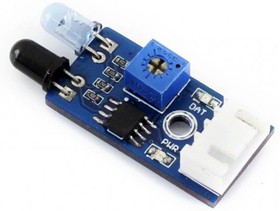
figure 1-Infrared distance sensor
Almost any object emits different thermal radiation, which is fixed by infrared motion sensors. With the help of a special system of lenses and special mirrors IR radiation of objects falls on the Central sensor. When objects move, there is a change in these systems of infrared radiation, which leads to the reaction of the sensor. The quality of IR sensors motion detection directly depends on the number of lenses and mirrors systems located in them.
Main disadvantages of infrared motion sensors:
– the probability of false positives of this type of sensors (exposure to any warm air flow);
– low accuracy of the response of the sensor in an open space (influence of rain, or sunlight);
Low operating temperature range
– inability to react to objects that do not transmit IR radiation.
Advantages of infrared motion sensors:
– a huge range of recording movement and also adjustment need ula capture control zone;
– the response of the sensors solely on the objects that have their own temperature;
Guaranteed safety of IR sensors for human and animal health (sensors do not emit radiation).
- ГОСТ 12.1.001-89 Ультразвук. Общие требования безопасности.
- Шайдуров В.В. Непомнящий О.В. Вейсов Е.А. Математика, механика, информатика. Построение математической модели преобразователя ультразвукового сигнала с целью практической реализации микропроцессорной системы сканирования высокотемпературных изделий.
- Васильев Е.Н. Деревьянко В.В. Программный комплекс для расчета температурных полей.
- Сенько В.Ф. Энергетическая электроника: Учебное пособие/ В.Ф. Сенько, А.В. Вовна, А.А. Зори. – Донецк: ДВУЗ «ДонНТУ», 2014. – 312 с.
- Жданкин В.К. Приборы для измерения уровня// Cовременные технологии автоматизации. – 2002 – № 3.
- Источники электропитания радиоэлектронной аппаратуры: Справочник/ Под ред. Г.С. Найвельта. – М.: Радио и связь, 1986. – 576 с..
- Коломбет Е.А., Юркович К., Зодл Я. Применение аналоговых микросхем. – М.: Радио и связь, 1990.- 320 с.
- Гутников В.С. Интегральная электроника в измерительных устройствах/ В.С. Гутников. – М.: Радио и связь, 1988. – 256 с.
- Изъюрова Г. И. Расчет электронных схем/ Г. И. Изъюрова. – М.: Высшая школа, 1987. – 153 с, 194 с.
- Матвеев А.Н. электричество и магнетизм. Учебное пособие – М.: высшая школа, 1983 – 463 с.
5.2 laser sensors
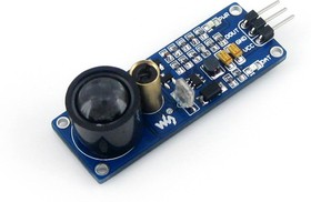
figure 2 - laser distance sensor
When it comes to the laser sensor, the following options should be preferred by experienced professionals:
Laser distance sensor Arduino – this device has established itself in the domestic market as one of the most reliable and high quality.
High precision laser distance sensors – in this case, a laser beam is used to measure the distance. During the measurement, the resolution can be set from 0.01 mm to 0.1 mm.
– laser sensors distance phase type – such a device measures the distance and shape of the object in obtaining the phase difference between the response phase and the return phase. The use of sensors of this type greatly simplifies the work of a specialist and makes it several times more convenient.
5.3 Ultrasonic transducers
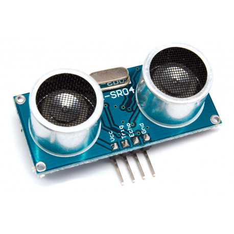
figure 3-Ultrasonic distance sensor
Ultrasonic vibrations (ultrasonic) create in the air, which is an elastic medium, moving pressure waves with a frequency range of more than 20 kHz; in other media, ultrasonic waves propagate with other frequencies. The ability of ultrasonic testing to spread in different environments is used in non-destructive testing systems, sounders, level transmitters, ultrasonic medical diagnostic systems, proximity sensors of industrial process automation systems, etc.
In that case, if there was a preference for the sensor required for distance measurement, ultrasonic type, you should choose three of the following options:
– ultrasonic distance measurement sensor HC sr04 product has permission from 2cm to 400 cm is designed to measure large-scale objects.
– ultrasonic distance sensors Promsitech – one of the most popular options in Russia. According to statistics, it is chosen by about 67% of the total population.
The Basic principle of operation of this type of sensors is the study of the control system using ultrasound, the frequency of which is not available for human ears. The ultrasound is sent to the entire area controlled by the sensor, and then it is returned back. The time between the moment of sending the signal and the moment of receiving the reflected signal is calculated. In case of distortion of information about the objects triggered a certain function of the sensor.
6. Development of the block diagram of the device
6.1 Rationale for the temperature dependence
figure 4 – ultrasonic distance sensors
The due to a single formula programmed in the memory of the microcontroller, with the change in temperature begins to appear temperature measurement error, which is directly proportional to the temperature increases with a large deviation from the nominal value. To correct this temperature factor in the block diagram of the device introduced a temperature measuring channel, which consists of a temperature sensor, measuring bridge, amplifier and leads the amplitude of the received signal to the input format of the analog-to-digital Converter, matching the input signal to the digital input of the microcontroller. According to the results of temperature measurement, the microcontroller introduces a correction to the measurement result using a deliberately programmed formulas for calculating the temperature correction.
This graph clearly shows the deviation of the ultrasonic sensor readings depending on the temperature.
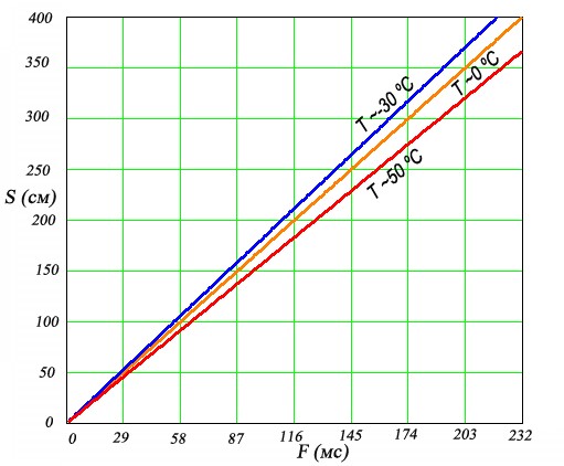
figure 5 – the dependence of the measurements from the test within
6.2 block diagram of the device
Based on the above facts, a block diagram of an electronic device was developed in which a temperature measurement channel was introduced. With the help of this channel, a correction factor is introduced into the standard distance calculation formula, which practically removes the temperature error of ultrasonic measurement. Further, the microcontroller operates according to the prescribed algorithm and transmits the appropriate commands either to the display unit, if any, or to the matching unit with the actuator that activates or changes the state of the power units of the platform.
Below is a block diagram of an electronic distance measuring device.
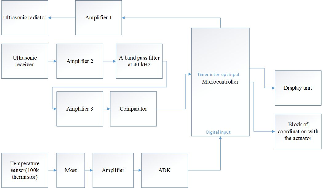
Figure 6-Block diagram of the electronic distance measuring device
Conclusions
In the course of the thesis was an analysis of existing methods of distance measurement, the most suitable, namely the ultrasonic method of distance measurement. However, having carried out calculations in different temperature conditions, a defect of this method was revealed, after which an additional channel for measuring the ambient temperature was introduced to introduce a correction factor. As a result, we can say that the device is several times higher than the accuracy of measuring the distance to the obstacles of moving objects compared to its prototype. This increase in the accuracy of measurements was achieved by entering a temperature measurement channel into the device, and the correction of the formula for calculating the distance to obstacles.As a result, the device has all the necessary characteristics for use in different temperature conditions.
Master's work is devoted to the development of the device orientation and determining the distance to the obstacles of moving objects in different weather and temperature conditions.
Based on the chosen method and prototype, a block diagram of the measuring system was developed.