
Abstract
Content
- Introduction
- 1. Relevance of the topic
- 2. The purpose and objectives of the study, the planned results
- 3. Brief description of the equipment of fan installations of the main ventilation of coal mines
- 4. Development and description of the operation of the block diagram of the device
- 5. Selection of the measuring transducer
- Findings
- References
Introduction
ТеорияThe theory and practice of diagnosis should be developed on the basis of the principles of indivisibility, with the effective use of universal diagnostic methods and tools. In this direction, great possibilities are opened by the methods of vibroacoustic diagnostics, based on the wide use of information, which is embedded in the oscillatory processes that accompany the functioning of machines and mechanisms.
Vibroacoustic diagnostics, which is one of the sections of technical diagnostics, has a number of features that separate it into a separate branch of knowledge. The main distinguishing feature of acoustic diagnostics is the use of not static parameters characterizing the state of the mechanism (temperature, pressure, oil or fuel oil composition, etc.) as a source of information, but dynamic parameters causing the appearance of acoustic waves propagation both in the mechanism and in the environment . The form of diagnostic information contained in the oscillatory process, regardless of the nature of its occurrence and the means of registration, is diverse. The wide frequency and dynamic ranges, low inertia, high propagation velocity cause a quick response of the acoustic signal to a change in the state of the object, which is an indispensable quality in emergency situations when the determining factor is the speed of diagnosis and decision making.
Equipping machine units with automated computer-based diagnostics systems that allow real-time diagnosis based on analyzing not only the spectral characteristics of oscillatory processes, but also the fine structure of the acoustic signal.
The tendency to specialization of methods and means of diagnosing individual components and elements of the mechanism and the complication of algorithms for the formation of diagnostic features and the procedure of diagnosis is not accidental. The need to move from monitoring the performance of a technical object to diagnosing incipient defects leads to the need to search for diagnostic signs that respond to minor deviations of technical parameters from the norm.
1. Relevance of the topic
For a variety of reasons, defects are quite frequent, leading to a significant increase in vibration, which not only has a harmful physiological effect on the body of people working with it, but also reduces the life, reliability and accuracy of machines and mechanisms. Instrumental vibrocontrol of the technical condition of the units of fan installations, in general, is carried out only under conditions of balancing and centering. Therefore, the late detection of such defects and the lack of a number of necessary automatic protections that respond to the equipment reaching an emergency technical condition is the cause of significant failures, the elimination of which requires considerable material and financial costs and time.
For example, the imbalance of the impellers of main ventilation fans occurs with a probability of 0.216 and is the cause of the increase in vibration in almost 50% of cases. This defect often leads to bearing failures, and the reliability of its recognition without the use of special tools, calculated by the method, does not exceed 0.587. At the same time, according to the energy-mechanical service of Donetskugol, the cost of replacing one bearing is 8–9 times higher than the cost of balancing work.
All of the above, as well as the importance of trouble-free functioning of fan and pumping installations for the life support of the main technological processes and the tendency to reduce the professional level of staff, have as the main task the task of improving the efficiency of maintenance and repair (TOR) through the use of automated continuous and periodic diagnostics of both working machines and their drive motors, will increase the reliability and olgovechnost fan and pump systems, to warn the harmful effects of vibration and reduce the cost of repairs due to timely detection of defects and warnings of destruction machine units.
2. The purpose and objectives of the study, the planned results
The purpose of this work is to develop a block diagram of the device to improve the reliability and durability of fan installations, prevent the harmful effects of vibration and reduce the cost of repairs due to the timely detection of defects and prevent the destruction of machine components.
3. Brief description of the equipment of fan installations of the main ventilation of coal mines
The fan units of the main ventilation of coal mines are designed for the mine ventilation systems of the main ventilation of mines and mines and consist of a working and backup electric fans, control devices, equipment operating mode (supply and pressure), bearing temperature control equipment, remote and automated control equipment, protection and alarm equipment, a set of means for reversing the air flow and transfer from a working fan to the cut an explicit, head, underwater and air ducts, building structures (buildings, foundations, diffusers, silencers, and so on. d.).
Ventilating units of the main ventilation are placed, as a rule, in a room on the surface of the earth near the mouths of hermetically sealed trunks, holes, boreholes and tunnels. They let the air through, which passes through the existing mines of a mine or a mine, with the exception of dead ends.
Mine fans, designed for the mine fan installations of the main ventilation, are manufactured in accordance with GOST 11004-84 Donetsk Machine-Building Plant named after. Lenin Komsomol, with a impeller diameter of 3 m and more and Artyomovsk Machine Building Plant with a impeller diameter of up to 3 m. The standard applies to fans with a nominal flow of 25 to 630 m3 / s and a nominal total pressure of 1000 to 12500 Pa when working with air that has a density of 1.2 kg / m3, dust content up to 150 mg / m3 and relative humidity up to 98 percent (at a temperature of 298 K), at an altitude of up to 1000 m above sea level. Fans can also be used in ventilation systems for ventilation of large workshops of metallurgical, chemical and other industries, where their working conditions are the same or close to the main conditions of the specified standard and if they comply with the requirements of current regulatory and technical documentation.
Mine fans main ventilation, depending on the direction of movement of the air flow in the impeller are made of two types:
Centrifugal fans on the design of the impeller are divided into:
Single-sided centrifugal fans have a single-inlet impeller, and double-sided impellers are double-sided. Axial fans on the design and the number of impellers are divided into:
Mine fans are used to transport mine air with a slight increase in its pressure and are turbomachines, in whose impellers an increase in the specific energy of the air occurs due to the interaction of the blades of the wheel with their surrounding flow.
In centrifugal fans, the air flow through the inlet in the axial direction is sucked from the suction or absorbing (in a double suction fan) boxes into the impeller, where it deflects by 90 ° in the inter-blade space of the impeller and under the action of centrifugal forces is thrown by the blades in the radial direction into the spiral housing (casing), which vents air in the desired direction, while partially transforming the dynamic pressure of the flow into static. In axial fans, the air flow enters the impeller in the axial direction and is discharged from the interscapular space also in the axial direction, for example, into the diffuser and then into the atmosphere (when the fan operates on suction).
Mine fans are characterized by the following parameters:
- feed Q (m3 / s);
- static pressure Psv (Pa) or total pressure Py (Pa) (depending on whether the fan is working on the suction or discharge);
- power of the electric drive N (kW);
- static ηs or full η efficiency
The aerodynamic qualities of the fans are estimated by individual aerodynamic characteristics, which are plotted as graphs of the values of Psv, N and ηs for a given impeller diameter, for a given frequency or rotational speeds (with an adjustable drive), at certain angles (θ) of blade installation (flaps) impeller, guides and rectifying devices when working with air, which has a density of 1.2 kg / m3. The aerodynamic characteristics of the fans are built according to the aerodynamic tests, which are carried out according to GOST 10921-74. The point of intersection of the pressure curves of the fan installation and the mine ventilation network determines the specific mode of operation of the installation. The set of modes in which the fan operates stably and economically (ηs ≥ 0.6) forms the working area of the fan installation.
4. Development and description of the operation of the block diagram of the device
The block diagram of the microprocessor-based vibration control system being developed is shown in Figure 1 In this figure:
D – vibration sensor;
SU – matching amplifier;
R – rectifier;
F – bandpass filter;
OU – normalizing amplifier;
M – multiplexer;
ADC – analog-to-digital converter;
MP – microprocessor;
PC – personal computer.
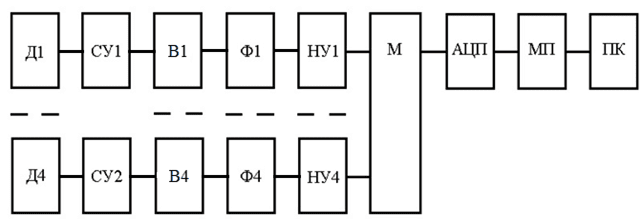
Figure 1 – block diagram of the microprocessor system
Taking into account the fact that spectral analysis is used to diagnose mechanism malfunctions, the variant of the scheme looks better when combined using software and hardware signal processing. Since the construction of the spectrogram requires large computational powers, then a PC (for example, a notebook type) with the appropriate software is used for this. Since the vibration acceleration signal is received from the sensor (ABC 017-04), and the vibration velocity signal is used for analysis, the vibration acceleration signal will be integrated by hardware. The piezo sensor has a high output impedance, so an amplifier is installed at its output, which matches the large input impedance. The filtering necessary to limit the spectrum of the signal under investigation before time sampling is performed by a band-pass filter with a frequency band of 5–2000 Hz. The microprocessor controls the collection of measurement information from various channels and its transfer to a PC via RS-232 interface.
5. Selection of the measuring transducer
The most optimal indicators have piezoelectric accelerometers. Accelerometers are devices designed to measure acceleration. Piezoelectric acceleration transducers are active transducers, that is, they create a measuring voltage without applying voltage to them from an external source.
The piezoelectric acceleration transducer consists of a housing 6 with a threaded hole 7 for mounting on the mechanism (2), electrical output 4, damping 3, spring 5, seismic mass 1 and piezoelectric element 2. Piezoelectric acceleration sensors are absolute vibration transducers. According to Newton's second law, in order to set the mass in motion, force is needed:

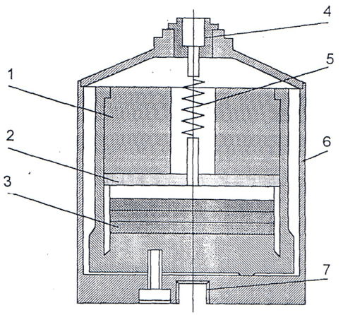
Figure 2 – Piezoelectric acceleration transducer
In piezoelectric acceleration sensors, the driving force is transmitted from the object to the seismic system built into the sensor, consisting of a seismic mass, a spring, and a damper. The seismic system, in turn, creates a corresponding force, which acts on the piezoelectric sensing element, on the surface of which an electric charge is created, hence the electric voltage, is proportional to the acceleration. For further processing of this voltage, we need amplifiers with extremely large input resistance.
To obtain the widest possible operating frequency range of the acceleration converter, its characteristic frequency should be as high as possible (the mass is small, the spring is very rigid).
Damping is used to reduce the conversion factor at the resonant frequency, while the optimal damping is D = 0.65. The operating frequency range of optimally damped systems ranges from 0 to 60% of the characteristic frequency of the converter. Seismic mass m is acted upon by forces;
– inertia
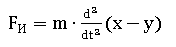
where x – is the mass displacement relative to the device body; y – movement of the body relative to the inertial space;
– damping
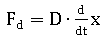
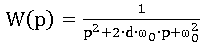
where D is the damping coefficient;
– elastic

Where c is the coefficient of elasticity.
The sum of these forces is equal to
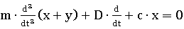
Or
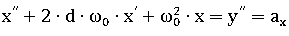
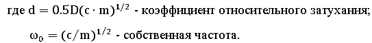
The transfer function of the accelerometer is:
Dynamic errors of accelerometers are determined by the relative attenuation coefficient d and the ratio between the natural frequency w0 and the acceleration frequency w.
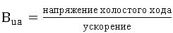
All other characteristics are given to estimate the errors. For longitudinal excitation, the no-load electrical voltage is determined by the formula:
where F (t) is the force acting on the sensor; And - the area of the electrode; d is the electrode thickness; g is the piezoelectric pressure constant.
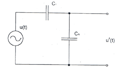
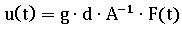
Figure 3 – The equivalent circuit of the piezoelectric acceleration transducer
Figure 3 presents the equivalent circuit of the piezoelectric acceleration transducer, constructed taking into account the internal capacitance of the sensor C and the capacity of the cable Sk.
Piezoelectric acceleration sensors have a transmission characteristic that is characteristic of a low-pass filter with resonance. The lower cutoff frequency of such converters depends on various influencing quantities, and the decisive influence on the mode of their operation at low frequencies is found in the design of the converter, the amplifier, and the quality of the installation, as well as operating temperatures, are used.
Figure 4 shows the fundamental frequency dependence of the relative voltage transfer ratio of the piezoelectric acceleration sensor.
Figure 4 – Frequency dependence of the relative voltage transfer ratio of the piezoelectric sensor
The designation fi (Fig. 4) corresponds to the electric boundary frequency (≈ 0.05 Hz), the designation f0 corresponds to the normalized frequency (≈ 1 kHz), and the designation fR corresponds to the resonant frequency (≈ 20 kHz). For practice, the frequency range ends at 0.3fR.
However, the frequency range of the piezoelectric sensor as a mechanical oscillatory system depends not only on its natural frequency, but also on the magnitude of the input resistance of the amplifier, to which the signal arrives. The sensor, together with the connecting line and the input resistance of the amplifier, forms the RC circuit, the resonant frequency of which depends on the size of the RC. The greater the capacitance of the sensor and the input impedance of the amplifier, the higher the resonant frequency of the circuit. The possibilities of increasing the sensor capacity are severely limited by design and technological factors. Therefore, it is necessary to increase the input impedance of the amplifier and bring it up to several tens of MOhm. This circumstance imposes strict restrictions on the length, more precisely the capacitance, of the line connecting the sensor to the amplifier. If you use a long line, the capacity of which is large, then it will shunt the high-impedance input of the amplifier and significantly reduce the level of the input signal, especially its high-frequency components. Therefore, as a rule, a preamplifier with a large input impedance is included in the channel, located near the sensor. The signal from the preamplifier output is no longer critical to the length of the line and can be transmitted over long distances, since the next block has a low-impedance input.
Let us choose ABC 017–04 type piezoelectric accelerometer as the primary transducer. The main parameters of this piezoelectric accelerometer are given in table 1.
To obtain a signal proportional to the displacement or speed, the operations of integrating the signal from the accelerometer are introduced. With a single integration, the signal will be proportional to the speed, with double integration - the offset.
In rotary mechanisms, it is most expedient to connect sensors on bearing supports. Figure 5.4 shows the most optimal sensor connection points for main ventilation systems.
Thus, we can conclude that as primary transducers of the vibration control device of the shaft ventilation units of the main ventilation we select four piezoelectric accelerometers of the ABC 017-04 type, which will be placed on the bearings of the mechanism.
Table 1 – Characteristics of the accelerometer ABC 017-04
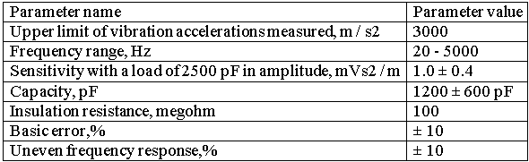
The relative transverse sensitivity of the accelerometer ABC 017-04:
– for group 1 – no more than 5%;
– for group 2 – no more than 10%;
– for group 3 – no more than 15%;
Additional temperature error of the accelerometer АВС 017–04 – no more than ± 0.15% at 1 °С;
The basic error is no more than ± 10%.
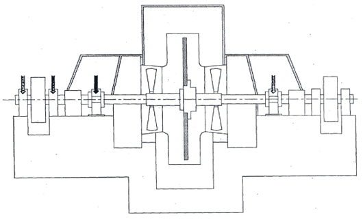
Figure 5 – Sensor Installation Locations
Findings
A description and classification of the mine fans used in the mines, as well as their main technical parameters are given.
Taking into account the results of research, a justification of the structural scheme of the device that is being developed has been carried out. Conducted a reasonable choice of the type of primary converter.
References
- Демченко С.И., Кузнецов A.B., Паршинцев В.П. "Неисправности шахтных вентиляторных установок главного проветривания: Справочное пособие" – М.: Недра, 1990. – 188с.
- Керстен Й.О. Аэродинамические испытания шахтних вентиляторних установок: Справочное пособие. – М.: Недра, 1986–196 с.
- Гращенков Н.Ф., Петросян А.3., Фролов М.А. й др. Рудничная вентиляция: Справочник – М.: Недра, 1988–440 с.
- Балицкий Ф.Я., Генкин М.Д. Виброакустические процессы в машинах и присоединенных конструкциях. – М.: Машиностроение, 1974–182 с.
- Биргер Й.А. Техническая диагностика. – М.: Машиностроение, 1978–240с.
- Артоболевский Й.Й., Бобровницкий Ю.Й., Генкин М.Д. Введение в акустическую динамику машин. – М.: Машиностроение, 1979–296 с.
- Генкин М.Д., Соколова А.Г. Виброакустическая диагностика машин й механизмов. – М.: Машиностроение, 1987–288 с.
- Макс Ж. «Методы и техника обработки сигналов при физических измерениях» – М.: Мир, 1983–268 с.
- Ивановский И.Г. Шахтные вентиляторы: Учеб. пособие. – Владивосток: Изд-во ДВГТУ, 2003–196 с.
- Сидоров В.А. Границы различения технических состояний машин. Вибрация машин: измерение, снижение, защита «материалы 2-ой международной конференции» / Сидоров В.А., Сидоров А.В. // ДонНТУ, Донецк, 2003–248с.
- Барков А.В. Мониторинг и диагностика роторных машин по вибрации. / Барков А.В., Баркова Н.А., Азовцев А.Ю. // Ассоциация ВАСТ, Россия, С-Петербург, 2000
- Гольдин А.С. Вибрация роторных машин: – 2-е изд. исправл. – М.:Машиностроение, 2000–344 с.
- Баркова Н.А. – Неразрушающий контроль технического состояния горных машин и оборудования: учеб. пособие / Баркова Н.А., Дорошев Ю.С.. – Владивосток: Изд-во ДВГТУ, 2009–157 с.
- РД 03–427–01. Методические указания по проведению экспертных обследований вентиляторных установок главного проветривания. – Введ. 2002–04–01. – Госгортехнадзор РФ, 2001–47с.