


Abstract
List of content
Introduction
At all times, there is need of new materials that will have the better characteristics in comparison with the old ones and will be cheaper to manufacture. Composite materials - one of the directions for new materials, as in its diversity can cover any areas of application. But for them it is impossible to accurately predict future properties without extensive testing using a large amount of these materials. Impedance spectroscopy is one of the methods that will allow to determine some of these properties using the minimum amount of material and time.
The article presents studies for the development of an impedance measuring instrument, as well as structural, functional and schematic diagrams. Modeling and error estimation of the proposed model of the device was carried out.
Actuality of theme
Of all the heterogeneous materials, electrically conductive composite materials are most common in microelectronics and electrical engineering. Most often they consist of two phases: a dielectric and an electrically conductive filler, i.e. they belong to highly heterogeneous binary heterogeneous systems.
Based on the principles of classification of HM, according to the nature of the distribution of the filler in the binding CM, it can be simplifiedly divided into several large groups: ordered, statistical, and structured CM. The ordered matrix composite materials can be attributed to materials whose filler particles are in lattice points
, more or less regular. In statistical KM filler particles are randomly arranged. Composites in which the filler forms one-dimensional (chain), two-dimensional (flat) or bulk (frame) structures belong to structured CM. A special class are functional gradient materials. Their fundamental difference from other CMs is the change in properties (for example, effective electrical conductivity) along the chosen direction inside the body.
The impedance spectroscopy of heterogeneous systems is based on measuring and analyzing the dependence of the complex electrical resistance Z (impedance) on the frequency $f = {\omega}/{2 \pi}$ alternating current. It can be used to determine the structural features of the HS (distribution of particles of the electrically conductive phase over the volume of the dielectric matrix, the relationship of particles into clusters), microscopic parameters (cluster sizes, their local resistance) and other characteristics of the HS. The data obtained from the measurement of heterogeneous systems on alternating current can be recorded in the form of frequency dependences of the following complex values:
- Impedance Z = Z' + iZ" ;
- Admittance Y = 1/Z = Y' + iY" ;
- Complex capacity, calculated as C = Y iω;
- Electrical complex M = 1/ ε = iωC0 Z = M' + iM",где M' и M" — Real and imaginative parts.
Z(ω) dependency analysis can be performed in various ways. The main and most illustrative is the construction of equivalent circuits (ES) substitution. An equivalent circuit for determining is understood as a model electrical circuit consisting of idealized resistors, capacitors, inductance of coils and having a frequency dependence, which investigates the HS. Horizontal schemes must be defined as a heterogeneous system. Added new items that clarify and complement the ES.
The impedance or impedance of a material may depend on many factors. Therefore, to determine the physical properties of new materials, such as corrosion resistance or electrical conductivity.
Substitution model
Using impedance spectroscopy, one should keep in mind that a single impedance spectrum is difficult to interpret unambiguously, even at the level of searching for an equivalent circuit (spectra of completely different electrical circuits can be very similar). Additional information to clarify equivalent replacement schemes and analysis of HS can be obtained by measuring the frequency dependences of Z in various conditions. For example, at different temperatures or with the additional imposition of an external electrical potential difference. At the same time, the contributions of various factors to the full response of the system to the effects of alternating current change, which allows, firstly, to more reliably determine the type of the equivalent circuit, and second, to track the change of each of the response components associated with a particular element of the equivalent circuit. Such an approach is especially productive in the study of electrochemical reactions in the thin electrode layer and the products of such reactions.
A visual representation of the behavior of the frequency dependence of Z can be made by constructing its hodograph. Hodograph will be understood as the trajectory described on the complex plane by the vector Z.
Example of substitution scheme:
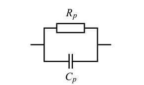
Figure 1 – Parallel substitution scheme.
Equation for a parallel equivalent circuit:
$$(Z'-\frac{R_{p}}{2})^2+Z"^2=(\frac{R_{p}}{2})^2$$
Measurement method
To measure impedance or complex resistance, an ammeter-voltmeter method is used, in accordance with which the sample under study is connected to the generator and the voltage drop across it and the current flowing in the circuit at different frequencies, as well as the phase shift between them is measured. The following algorithm will be used for measurement:
- MC sets generation frequency;
- waiting for setting values at the outputs of measuring units;
- if the value of the impedance modulus is close to the extreme values of the ADC of the MC, switch the range;
- save the measured values;
- repeat;
The figure shows the proposed scheme that implements this algorithm..
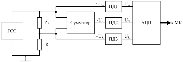
Figure 2 – Functional diagram of the impedance meter
In this circuit, the sample is connected in series with the reference resistor R. The voltages from the input and output of the divider are summed using an adder. Further, using peak detectors PD1-PD3, the amplitude values of the measurement signals are obtained and converted to digital form using the ADC. Next, the microcontroller calculates the impedance value of the sample under study. Below are the calculation formulas.
Phase shift:
$$\phi = acos(\frac{U_{S}^2-U_{G}^2-U_{R}^2}{2 U_{G} U_{R}})$$
where U_{G}, U_{R} and U_{S} are the amplitudes of the voltages at the input of the divider, the output of the divider and the output of the adder, respectively.
Module impedance measuring divider:
$$\vert\dot{Z_{C}}\vert=\vert\dot Z_{X}+R\vert =\vert R\frac{U_{G}}{U_{R}}\vert=R\frac{U_{G}}{U_{R}}$$
From the expression (2) we obtain the complex resistance of the sample:
$$\dot Z_{X}=\dot Z_{C}-R=\vert \dot Z_{C}\vert (cos(\phi)+jsin(\phi))-R$$
Real and imaginary parts of the sample impedance:
$$Re(\dot Z_{X})=\vert \dot Z_{C}\vert cos(\phi)-R=R(\frac{U_{G}}{U_{R}}cos(\phi)-1)$$
$$Im(\dot Z_{X})=\vert \dot Z_{C}\vert sin(\phi)=R\frac{U_{G}}{U_{R}}sin(\phi)$$
Simulation
For the operation of the device, a generator of sinusoidal oscillations with a frequency tunable in a large frequency range and control using an MC is required. This makes capacitor type three-point generators and a generator on the Vin bridge not applicable due to the complexity of control. The DDS (Direct Digital Synthesizer) generator is most convenient for this, and since the development of such a generator is not economically feasible and in terms of reliability, the ready-made MCU-9833 module was selected
Impedance modulus is indirectly measured as the ratio of the measured voltage to the measured current. Peak detectors are used for the measurement, the circuit of which is shown in the figure:
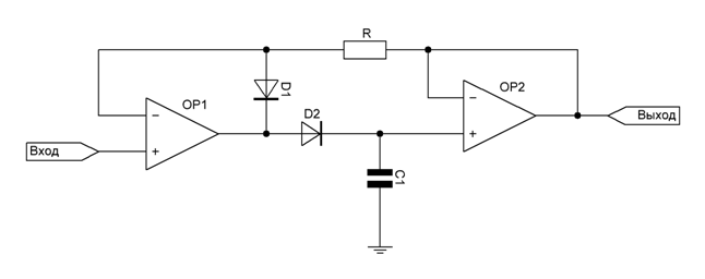
Figure 3 Peak-detection circuit
To obtain the sum of the voltages Us, a voltage adder is required, it is represented below:
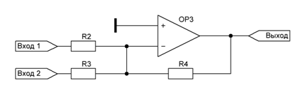
Figure 4 Adder circuit
Next, to test the selected scheme, the Proteus model was built:
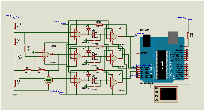
Figure 5 – Proteus model
To test the model, we set the values of the series-connected resistors RX and CX of the capacitor to 80 Ohm and 1.2 uF, respectively.
Now let's check what value the model will display: 
Figure 6 – Model output
As you can see, this model provides a measurement result with an accuracy of 1.5%, the main error arises due to the ADC resolution of the MC. Other errors due to the bias of the operational amplifiers and the discharge of the capacitors of the peak detectors are much less than the error of the ADC and can be ignored.
As a result, the Proteus model was obtained, the circuit diagram of the device is ready for assembly.