
Abstract
Content
- Introduction
- 1. Relevance of the topic
- 2. The technological part
- 2.1. Principle of operation of the CCM
- 2.2. CML crystallizer
- 2.3. Formation of solid crust of continuously cast ingot and heat exchange in the crystallizer
- 3. Combined control reaction at harmonic input
- 3.1. The principle of combined management
- 3.2. Driving device at sinusoidal input harmonic influence
- 4. Synthesis of combined control system
- 4.1. Synthesis of combined speed control system
- 4.2. Analysis of the combined speed control system
- 4.3. Synthesis of position control system
- 4.4. Analysis of the combined position control system
- Conclusion
- Source list
Introduction
The mechanism of swing of the mold is a part of the technological equipment of the machine of continuous casting of preparations (CCM) and is intended for ensuring oscillatory movement of the mold according to the set parameters. It is required to ensure high accuracy of oscillatory movements of the mold, since if there is an error in amplitude and phase shift from the set value, this can contribute to the emergency mode of the caster, in which a hot jet of metal can break through the metal crust, which will lead to a malfunction of the machine and cause a dangerous situation for the lives of workers. Also, the elimination of errors contributes to an increase in the speed of steel casting, which will lead to the productivity of the caster. For this reason, this paper investigates a way to improve the accuracy of working drives control harmonic effects. To improve the accuracy of the signal processing by the control action, a combined control is introduced into the system. To implement this method, it is required to perform the operation of differentiation of the control signal. To implement this method, signal differentiation is realized without direct differentiation.
Also in this paper we study the synthesis of regulators of all circuits, in which all the regulators of the system should work in normal mode.
1. Relevance of the topic
The object of development and research is the drive of the swing mechanism of the mold.
The purpose of the work is to develop and study ways to improve the accuracy of the harmonic input effects of the drives.
Development is carried out on the basis of provisions of the theory of the electric drive, the theory of electric cars and control systems of electric drives. Studies of the system were carried out by mathematical modeling using the software Matlab.
The study of combined control without direct differentiation is carried out, the functional scheme of the electric drive with combined control from the harmonic driving influence is considered. With the help of the model of the electric drive system, the development of the control harmonic effect on the speed circuit and on the position circuit by the drive is studied. The performed developments can be applied at carrying out improvement of system of the electric drive of swing of the mold in the machine of continuous casting of a preparation. With the improvement of quality, the quality of products on the CCM will increase, which is a big plus for the industry.
2. Technological part
2.1. Principle of operation of the caster
The main technological function of any CCM is the transformation of steel from a liquid state to a solid state, as well as obtaining a certain geometric shape for the workpiece and the implementation of the qualitative characteristics of its surface and internal structure.
In order to achieve a solid state of the workpiece, it is necessary to remove some amount of heat to the environment for a certain amount of time. In order for the cooling process to be carried out normally, it is necessary to ensure smooth movement of the steel, at a certain speed with proper heat dissipation[1].
The main link of this technology is a continuous casting machine, a generalized scheme of which is shown in figure 2.1.

Figure 2.1 – General scheme of steel casting on the CCM
Main functional elements of the CCM:
– steel casting stand (1) – it houses steel casting buckets (2), moves them from the standby position to the casting position and back, provides batch casting, lifting and lowering of buckets during casting, and for continuous weighing of buckets with metal;
– intermediate bucket trolley – it is needed to support the bucket during casting and moving from the standby position to the working position;
– intermediate ladle (3) – with the help of it, the metal enters the mold with a clear flow rate of a well–formed jet, so that the steel is poured simultaneously into several crystallizers, which carries out serial casting, the so–called floating on melting
, with the change of steel ladles without stopping the casting as well as without reducing the casting speed; the intermediate ladle is a buffer capacity, since it coordinates the flow of metal from the steel ladle to the mold;
– crystallizer (4) – it is used for receiving liquid metal and forming a workpiece of a certain section, and also serves for primary cooling (cooling occurs during pouring with water);
– the mechanism of reciprocating motion of the mold (5) – is necessary to prevent breakouts of the ingot crust at the outlet of the mold and provides a complete healing
of the rupture site, which occurs during the movement of the workpiece in the mold;
– secondary cooling zone – here there is a complete solidification of the cast ingot, uniform cooling of the ingot is provided (water is sprayed by nozzles (6), the geometric shape is maintained by rollers (7) (bulging is prevented);
– pulling–correct machine (TPM) – is used to pull the cast workpiece from the mold as well as to align it on the radial and curvilinear devices and feed it for further cutting to the mechanism; TPM provides the feed of the seed into the mold and keeps it in the mold in the process of sealing gaps, etc.;
– machine (mechanism) for cutting workpieces (8) – serves for cutting continuously cast metal to certain lengths;
– priming (9) – provides the formation of a temporary bottom
in the mold before starting the casting, as well as for subsequent pulling with the coupled workpiece TPM;
– electromagnetic mixing device (10) – improves the quality of the workpiece.
The supply of steel to the mold begins only after the mold is filled with metal at 30–40% of its nominal capacity[2].
")
Figure 2.2 – The work of the mold (1 – mold, 2 – drive, 3 – the bucket)
Animation, 12 frames, size 50.8 KB
As soon as the inner cavity of the mold is filled with metal, the process of priming down begins. The speed of ingot extraction depends on the thickness and mechanical strength of the solid crust of the ingot at the outlet of the mold. The crust is necessary in order to prevent the breakout of the liquid metal during casting.
To ensure that the hard crust does not stick to the surface of the mold, the mold performs a reciprocating motion with a certain amplitude and frequency during casting. The level of metal in the mold must be kept constant to ensure high quality ingot, as well as a stable casting process.
2.2. The continuous casting mold
The mold is one of the most functionally important units that determine the rational operation of the caster and the optimal condition of the continuously cast workpiece.
2.3. Formation of solid crust of continuously cast ingot and heat exchange in the crystallizer
The mold is designed to receive liquid metal from the mill, and the transformation of the liquid steel into a solid state due to the intense heat dissipation of the coolant. The steel enters the mold by means of a submerged glass or simply by an open jet (figure 2.3)[3].
 and the slab caster using the submerged (right)")
Figure 2.3 – Supply of steel in the ingot mold open jet on a high-quality continuous casting machine (left) and the slab caster using the submerged (right)
Due to the formation of a hard crust in the mold, the workpiece is formed. Through the walls of the mold heat is released into the environment, this occurs during the formation of a solid crust. There is a risk of adhesion of the hard crust to the walls of the mold, the so-called tacking
, which leads to the formation of breakouts of the hard shell at the exit of the mold.
The peculiarity of the mold – enhanced heat dissipation from the workpiece. In the mold, the temperature of the steel in the liquid core of the workpiece must be at least a few degrees higher than the temperature of the beginning of solidification, the so-called liquidus temperature. The temperature distribution in the cross section of the mold, as well as the workpiece with the presence of a gas gap between the workpiece and the wall of the mold, provided in figure 2.4

Figure 2.4 – The character of change of temperature from the molten steel to the cooling water
The heat transfer strength depends on the following processes:
– convective motion of steel flows along the solidification boundary;
– intensity of heat removal through the hardened crust of the workpiece;
– heat transfer through the gas gap between the hardened shell of the workpiece and the inner surface of the mold;
– heat sink through the protective coating and directly to the copper wall of the mold;
– heat transfer to cooling water.
The stay of the metal in the mold should ensure the formation of a solid crust, sufficient that during the exit from the mold the workpiece has an acceptable strength, which will not allow breaks and cracks of the solid frame.
3. The reaction of the combined seal at the harmonic of the input exposure
3.1. Principle of combined control
To minimize the ratio of the swing parameters of the required values in transient modes, it is advisable to implement a combined control.
Under the combined understand such control, when along with the closed-loop control is used and open-loop control, in which the control signals involved impacts, as well as their derivatives. Open channels are used to ensure the invariance of the system, the organization of closed circuits reduces the sensitivity of the system to changes in parameters. Any combined system behaves better than a system that uses only deflection control.
There are combined control of the control and perturbing effects.
Combined control allows, in addition to improving the accuracy of tasks, also improve the performance of the system.
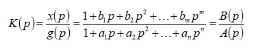
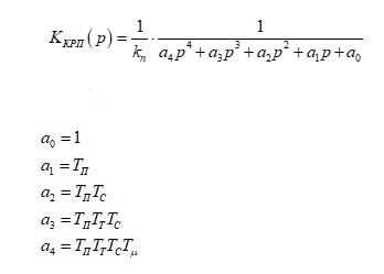
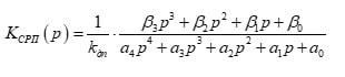
The PF of a closed system can in General be represented as the ratio of two operator polynomials:
3.2. The master device is at sinusoidal input harmonic influence
To implement the combined control, it is necessary to provide at the input of the system, in addition to the input harmonic effect, signals proportional to its derivatives. The number of derivatives is limited by the order of the closed loop control transfer function. It should be noted that in its pure form the use of differentiating links:
to isolate derivatives is impossible, and the implementation of real differentiating links:
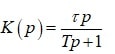
(in this form) is not advisable, because not only provides a forcing component, but also increases the order of the system. Since we use a sinusoidal harmonic signal, the realization of derivatives can be achieved without the use of differentiating links. In General, the memory can be implemented in the following way.[4]
As a task, we form a sinusoidal signal, and for the implementation of derivatives, it is necessary to form a cosine, using a combination of these signals, it is possible to implement the required number of signals derived from the sinusoidal setting effect without performing a differentiation operation:
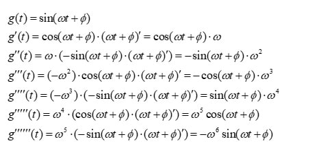

Figure 3.1 – Block diagram of the combined master device
In cases of need to implement the m–th order, where m=(2;3;4...), a control device is formed similar to the one shown in figure 3.1, only the number of correction links corresponds to the order of the combined control m.
4. Synthesis of combined control system
4.1. Synthesis of combined speed control system
Consider the implementation of the combined control on the example of the DC motor model, which was considered earlier.
The circuits of the system are set to the modular optimum, based on this we can calculate the coefficients b1–b3 for the implementation of combined control[5].

Figure 4.1 – Calculation block diagram of the third order
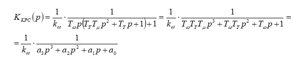
Transfer function of the master device:
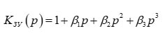
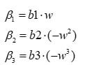
Where the coefficients of the transfer function bn will be equal, based on the model of the combined master device (figure 4.1):
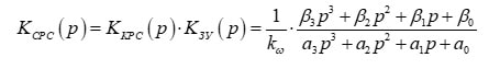
The transfer Function of the closed cattle:
With combined control, the transfer function will be:
The condition ensuring the minimum finite duration is achieved if:
4.2. Analysis of the combined speed control system

Figure 4.2 – Model of DC motor speed slave control system with combined control

Figure 4.3 – The simulation result of the CDS without the combined control

Figure 4.4 – The result of simulation of combined control SRS
As can be seen from the simulation results, the combined control eliminates phase shift in steady–state mode, as well as with increasing frequency, there is no amplitude error. This makes it possible to minimize the harmful effects of drives required to work in concert, for example for slab casters[7].
4.3. Synthesis of position control system
First, you need to adjust the position contour to the modular optimum. The block diagram is shown in figure 4.5.
The transfer function of position controller:
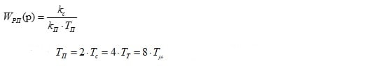

Figure 4.5 – Block diagram of regulation of position
Based on this PF position control loop:
In cases of realization of 3 derivatives in memory the transfer function of the closed combined system of regulation of position will have the form:
We calculate the coefficients b1, b2 and b3 in General, using the optimization algorithm for the modular optimum:
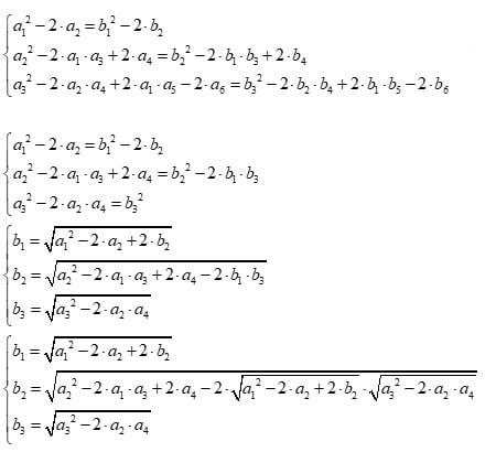
Further we will use numerical method to solve the system of equations.
4.4. Analysis of the combined position control system

Figure 4.6 – Model of the system of subordinate regulation of the position of the DC motor with combined control
We will conduct a study of the model for the development of harmonic effects. The task will be a sinusoidal signal, variable frequency, at the initial time is 7 Hertz, after 0.32145 seconds, the frequency increases to 10 Hertz.
In cases when we implement three derivatives in the master device, when m=3:

Figure 4.7 – The result of a simulation of the PSA
In figure 4.7, we observe the signal of working off the system with combined control in cases m=3, as can be seen, compared to working off the system without combined control, the result has improved, however, there is still a phase shift, as well as an amplitude error, of course not as large as without combined control. At a frequency of 7 Hertz, in steady-state mode, the amplitude error from a single setting effect is about 1%, and the phase shift is 0.01732 seconds. At 10 Hertz, the amplitude error increases to about 8%, and the phase shift is 0.0184702 seconds.
5. Conclusion
In the technological part of the system it is shown that the oscillation of the swing mechanism is carried out with a certain frequency and amplitude as a function of the speed of steel casting. With technological changes in the casting speed, it is necessary to change both the frequency and the amplitude of the oscillation of the mold. Depending on the phase–frequency characteristics of the control system, the phase shift and amplitude of the mold swing change when the actual working off from the set value, which forces additional measures to be taken in the control system to support the set amplitude and phase matching.
This problem is especially important for slab continuous casting machines, when due to the overall dimensions of the mold, the swing is carried out by means of two drives located on different sides of the mechanism, the work of which must be synchronized with each other.
The paper shows that the implementation of the combined control, with the order coinciding with the order of the external closed loop position control, provides an exceptionally high quality of oscillation. When there is no phase shift in steady–state modes, and the deviation from the specified amplitude is minimal.
Therefore, such combined systems are suitable for practical implementation in real control systems.
Source list
- Евтеев Д. П., Колыбалов И. Н. Непрерывное литье стали – Москва: Металлургия, 1984.
- Нисковских В. М., Карлинский С. Е., Беренов А. Д. Машины непрерывного литья слябовых заготовок – Москва: Металлургия, 1991.
- Смирнов А. Н., Антыкуз О. В., Цупрун А. Ю., Пильгаев В. М. Некоторые подходы к выбору рациональных параметров качания кристаллизаторов МНЛЗ / Электрометаллургия №5 2008.
- Коцегуб П. Х. Синтез вентильных приводов постоянного тока – Донецк, 1983.
- Коцегуб П. Х. Синтез и анализ комбинированной системы позиционного электропривода с цифровым П-регуляторами скорости и положения – Донецк, 1987.
- Коцегуб П. Х. Губарь Ю. В., Синтез комбинированной системы позиционного электропривода с цифровым ИП-регулятором – Донецк, 1985.
- Липковский К. А., Чермалых Т. В. Комбинированная система управления позиционным электроприводом с многоканальной задающей моделью / Техн. электродинамика, 1995.