


Abstract
Content
- Introduction
- 1. Theme urgency
- 2. Goal and tasks of the research
- 3. Researches and develompents review
- 4. Description of the upgraded design of the grinding wheel head
- Conclusion
- References
Introduction
The head radiolucent antenna cowl is an important element of modern high–speed aircraft controlled by radar guidance. Among the elements of aircraft, the geometrical parameters of which are determined by aerodynamic requirements, details of a living form are common. This type of parts is made of radiolucent non–metallic materials, in particular glass and ceramic. When grinding lively parts in circles with a straight generatrix, distortion of the generatrix of the profile of the outer surface of the part occurs. In domestic and foreign roll grinding machines, the method of rounding around with a profile in the form of an arc of a circle is widely used in the processing of large surfaces. Circles with a convex generatrix eliminate profile distortion [1].
1.Theme urgency
In modern industry, the manufacture of products from ceramic materials is widespread, due to their specific properties. These properties make fragile non–metallic structural materials, in particular, ceramic, the most suitable for use in aggressive environments of the ocean and space, in aircraft and rocket science. Due to the high hardness of the material, machining of the workpieces is possible only with an abrasive diamond tool. Obtaining the required surface quality after machining such parts depends on a number of factors, taking into account the fact that one of the important tasks of mechanical engineering is to increase the productivity of technological processes while reducing their cost [2].
High demands are made on the accuracy and quality of the machined surfaces of the parts, since the durability of machines operating at high speeds and loads depends mainly on the surface quality of the parts.
During the processing of a part, all the constituent elements of the TPS are affected by static and dynamic forces that vary in magnitude and direction, causing a relative displacement of the constituent elements of this system, both due to the selection of the inevitable clearances in moving and stationary joints, and due to the elastic deformations of the elements themselves and their contact surfaces.The magnitude of these displacements - the flexibility of the system depends on many factors: the magnitude of the acting forces, their combination in directions; quality and degree of wear of rubbing surfaces; the nature of the lubricant, etc. In connection with the variety of acting factors, it is difficult to determine in advance the magnitude of the resulting displacements and compensate them in order to increase accuracy.
2. Goal and tasks of the research
The aim of the work is to modernize the rotation drive, as well as the development of an automatic control system for the rotation of the grinding wheel head.
The object of study is the rotation drive of the grinding wheel head.
The subject of the study is the control of the process of forming the accuracy of the outer contour of the fairing made of ceramic in diamond grinding.
3. Researches and develompents review
Technological process product processing involves multi–step grinding processing as external and internal circuits on machines of the type RT 66202, equipped with aggregate grinding head and direct copying. The article presents the results of studies of dynamic the characteristics of the TPS when grinding the outer surface of the part, the scheme of which is presented in figure 1.
Figure1 – External processing of the product (animation: 10 frames, 10 retries, 132 kilobytes)
Features of product processing considered class of sitalls are largely due to following factors. The main dimensions of the product: length up to 1.0 m; maximum diameter 450…500 mm; workpiece wall thickness 20 mm at the thickness of the finished product is 5 mm. For processing the inner contour of a product approximately 18–20 hours of machine time are spent; processing of an external contour takes 6–10 hours at a significant proportion of manual labor used in finishing operations external profile processing. Product Performance require increased accuracy and quality requirements processing, in particular, ensuring a minimum depth of defect surface layer that determines the duration of subsequent chemical etching and hardening operations machined surfaces [4].
To increase accuracy the machining of the ceramic glass fairing must be leveled factors affecting her.
Main cause of errors formation on the polished surface of the product is a change position of the grinding wheel relative to trajectory defined by the shape and profile of the part. Reasons causing change of distance between the given and real trajectories shaping, are vibrations in the technological system processing, as well as inaccuracies in the geometric shape of the grinding wheel and the error of its installation [5].
Consider the factors affecting precision machining.
It is known that when grinding thin–walled shells of rotation (installation scheme of the workpiece on the machine shown in Figure 2) in the contact zone of the workpiece with the grinding wheel there are bending vibrations at two frequencies of 60 ± 5 Hz and 123 ± 10 Hz close to the natural frequencies of the subsistem spindle machine assembly – facility – workpiece
[6].
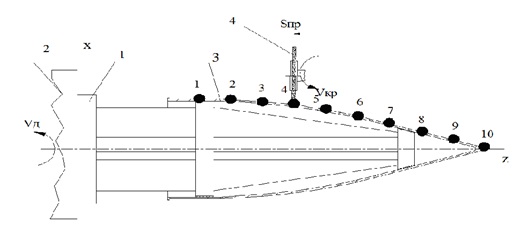
Figure 2 – The scheme of the technological system with an outer grinding of the workpiece – thin-walled shell of rotation from sitall: 1 – mandrel; 2 – machine spindle; 3– workpiece; 4 – grinding wheel 1A1 200x103x376 A 315/250–4–M2–01, mounted in the power head. Points 1…10 – points that limit the areas of variation of the parameters of the considered technological system
As shown by the analysis of the formation error of the processing of the outer contour of the product [7], the main processing error is associated with the displacement of the profiling point on the generatrix of the grinding wheel when it moves along the workpiece. The existing kinematic error significantly affects the accuracy of processing and can exceed the value of the dynamic by 10 times.
With an increase in the angle of rotation of the axis of the grinding wheel (in the plane of the axis of rotation of the workpiece and the longitudinal feed vector), the kinematic error decreases (fig. 3), and in the case of a worn wheel at α = 10° completely disappears. However, the problem lies in the impossibility of turning the grinding head at large angles (more than 5 °) due to the danger of touching the head body and the workpiece [7].
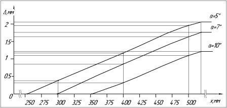
Figure 3 – Graph of the kinematic processing error depending on the angle of rotation of the grinding wheel axis[7].
Minimization of processing errors is the most important technical limitation when optimizing the grinding process from the conditions of maintaining a constant forming point. To reduce the kinematic error during the entire processing period of this workpiece, you can use a rotary device that turns the circle when it moves along the generatrix.
4. Description of the upgraded design of the grinding wheel head
In order to obtain a variable rotation angle of the grinding wheel, the design of a backlashless drive for turning the grinding headstock [8] was developed at the Department of Machatronic Systems of Machinebuilding Equipment of Donetsk National Technical University. The headstock is a two–stage cylindrical–worm gearbox with two spring–loaded worms. The output shaft of the drive – the shaft of the worm wheel – provides rotation of the table with a grinding head mounted on it.
We have modernized the backlashless drive of the device for turning the grinding head for a more complete use of the diamond layer of the wheel. The grinding wheel is moved to the opposite side of the turning machine, which prevents the grinding head from contacting with the workpiece. The use of such a design of the grinding head is possible only in systems with automatic control, since in this case the machine operator does not have the possibility of direct visual observation of the machnining process. The main advantage of this design is the ability to rotate the grinding wheel to the required angle from the condition of ensuring the constancy of the forming point on the grinding wheel when it moves along the contour of the workpiece, which will eliminate the kinematic error described above (fig. 4).
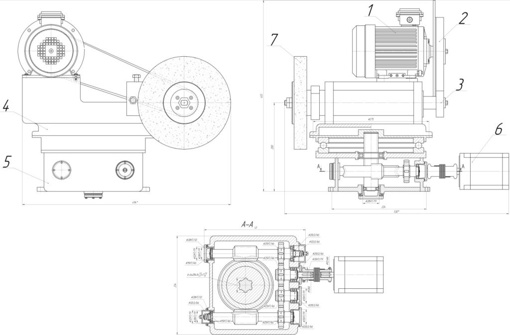
Figure 4 - Design of the upgraded grinding headstock and rotary device (1 – wheel drive motor, 2 – belt drive, 3 – spindle unit, 4 – housing, 5 – rotary device, 6 – rotary drive drive motor, 7 – grinding wheel)
A thrust bearing was used as the guiding element of the rotation device, which reduced the influence of the friction moment in the guides on the total moment of resistance to rotation. Based on the updated initial data, the gears of the gearbox were re–calculated to minimize the size of the rotary device.To select the motor of the rotary device, the dynamic characteristics of the drive were calculated. The total moment of resistance was determined by the formula:
During the calculation, the limiting angle is also determined at which it is necessary to expand the grinding wheel using the equation of the parabolic section forming the outer surface of the workpiece:
Differentiating the equation of the second section, we obtain the angle of inclination of the tangent at the end point of the parabolic section
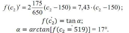
To ensure constant contact between the generatrix of the grinding wheel and the contour of the workpiece, it is necessary to adjust the angle of rotation of the grinding wheel axis along the entire length of the part. The limiting value of the angular acceleration of the system (during the transition from the conical to the parabolic part) is also determined, which is necessary for calculating the dynamic characteristics of the drive:
The value of angular acceleration allows you to determine the moment of inertia of the rotating structural elements of the rotary device.
Conclusion
The master's thesis is devoted to the design and study of a control system for the processing of thin–walled parts from ceramic. When writing this essay, the master's work is not yet completed. Final completion: June 2020. The full text of the work and materials on the topic can be obtained from the author or his leader after the specified date.
References
- Суздальцев Е. И. Радиопрозрачные, высокотермостойкие материалы ХХI века / Е. И. Суздальцев // Огнеупоры и техническая керамика. – 2002. – №3. – С. 42–50.
- Кальченко В. И. Шлифование криволинейных поверхностей крупногабаритных деталей. – М.:Машиностроение, 1979.
- Ситталы и их применение [Электронный ресурс]. Режим доступа: https://studopedia.su/10_156739_sitalli-i-ih-primenenie.html.
- Калафатова Л. П. Прогнозирование качества поверхностного слоя при обработке изделий из технических ситаллов // Приложение №9 к журналу
Инженерный журнал. Справочник
Инженерия поверхности. – М.: Машиностроение. – 2002. – №9. – С.5–8. - Калафатовa Л. П., Гусев В. В., Олейник С. Ю. Исследование динамического состояния технологической системы алмазно–абразивной обработки тонкостенных оболочек из ситаллов // Вісник СевНТУ: зб. наук. пр. Вип. 128/2012. Серія: Машиноприладобудування та транспорт. – Севастополь, 2012 с. 60–67.
- Гусев В. В. Исследование динамических характеристик элементов системы СПИД при шлифовании деталей сложной пространственной формы из ситаллов / В. В. Гусев, Л. П. Калафатова, И. С. Каракуц // Надійність інструменту та оптимізація технологічних систем. Збірник наукових праць. – Краматорск, 2007. – Вип. №21. – С. 148–155.
- Гусев В. В. Влияние кинематической погрешности шлифования на точность обработки антенных обтекателей / В. В. Гусев, Л. П.Калафатова, Д. В. Поколенко//Сучасні технології в машинобудуванні: Зб. наук.праць.
- Быхалов А. Г. Устранение кинематической погрешности обработкипри наружном глубинном алмазном шлифовании антенного обтекателя /А. Г. Быхалов, В. В. Гусев // Інженер. Студентський науково–технічний журнал. – Донецьк: ДонНТУ, 2007. – №8. – С. 34–37.