
Abstract on the theme of graduation work
Content
- Introduction
- 1. Relevance of the topic
- 2. Parameters and operating modes of the elements of the water injection complex
- 3. Analysis of existing solutions
- 4. Development of the concept of building self-propelled guns
- 4.1 Justification of the choice of control method of the pumping unit
- 4.2 Justification of the choice and expected results of the selected version of the ACS concept
- Conclusions
- List of sources
Introduction
Due to the existing technological and technical features, cement plants are energy-intensive enterprises. From 60 to 70 percent of the cost of a ton of cement is energy, the prices of which are growing from year to year. In powerful rotary kilns, clinker is fired by burning hundreds of thousands of cubic meters of imported natural gas. Thus, the problem of energy efficiency today is of particular importance both for the cement industry and for the economy of Donbass as a whole. The main direction of the economic strategy is the transfer of the cement industry to coal fuel, which will reduce energy costs for cement production and minimize the use of imported hydrocarbons. The use of modern coal mills solves the tasks, but this equipment has several disadvantages, which lead to unreasonable energy costs, increased equipment depreciation and cost of production. Currently, some of the existing enterprises using coal fuel are already equipped with modern coal mills, which are equipped with the necessary means and automation systems. First of all, it should be noted that in the automation of the main and auxiliary technological processes in the production of cement, individual developments and designs of automation systems and tools for a specific technological process in a particular enterprise are used. The existing process control systems for cement production enterprises lack standard, standard, unified automation solutions, including for a water injection complex.
As a rule, the monitoring and control functions of the water injection complex in a roller mill are implemented within the framework of a common automatic process control system with a vertical roller mill (or automatic process control system with a coal – grinding department), and not a separate self-propelled gun. This leads to the fact that the monitoring and control functions of the main parameters are performed, often according to simplified schemes and control principles, which leads to unsatisfactory control quality from the standpoint of modern requirements. In addition, part of the control functions is implemented remotely by the operator in manual mode, including the functions of controlling water injection. Existing systems for automatic control of the complex of water injection into roller mills of cement plants do not fulfill all the necessary functions for controlling and controlling the parameters of the control object under consideration. Therefore, the development of a system for the automatic complex of water injection in a vertical roller mill is relevant. The aim of this work is to increase the efficiency of the complex of water injection into a vertical roller mill by developing an automatic control system that will improve the reliability and safety of this facility, as well as reduce operating costs for the process of its functioning. Achieving this goal is possible due to an in-depth analysis of the features of this object management, development and implementation of the necessary control algorithms using a modern elemental base – programmable logic controllers, sensors and actuators. The aim of this work is to increase the efficiency of the complex of water injection into a vertical roller mill by developing an automatic control system that will improve the reliability and safety of this facility, as well as reduce operating costs for the process of its functioning.
1. Relevance of the topic
As a rule, the functions of monitoring and controlling the complex of water injection into a roller mill are implemented within the framework of a common automated process control system with a vertical roller mill (or automatic process control system by a coal – grinding department), and not a separate self-propelled gun. This leads to the fact that the monitoring and control functions of the main parameters are performed, often according to simplified schemes and control principles, which leads to unsatisfactory control quality from the standpoint of modern requirements. In addition, part of the control functions is implemented remotely by the operator in manual mode, including the functions of controlling water injection.
The considered automatic control systems for the complex of water injection into a vertical roller mill (operating at the Amvrosievsky cement plant Doncement and used at other mills) do not fulfill all the necessary functions for controlling and controlling the parameters of the control object under consideration. Therefore, the development of an automatic control system for a complex of water injection in a vertical roller mill in the conditions of the Amvrosievsky cement plant Doncement is relevant
2. Parameters and operating modes of the elements of the water injection complex
The tank with the corresponding fittings is designed for uninterrupted supply of water and smoothing out fluctuations in its flow rate that occur when the load on the roller mill and, accordingly, on the water injection complex change.
The object of regulation is a reservoir, the output controlled value of which is the water level HP (t), which depends on the flow rate of the supplied water QBX (t) and the current supply of the pump unit QH (t) . The mathematical description of the reservoir has the form [1]:
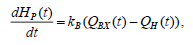
where dHp (t) / dt is the rate of change of level in the catchment, m / s;
QBX (t) - flow rate of water supplied to the tank, m3 / h;
QH (t) - pump flow, m3 / h;
kV - design coefficient of the tank:

where F is the area of the tank, m2 .
The efficiency of the water injection complex is influenced by a number of parameters of the pumping unit that determine its current state [4]:
- QH (t) is the supply of the pumping unit;
- H (t) - pressure (pressure) of the pumping unit;
- HB (t) is the vacuum gauge suction height;
- is the efficiency of the pumping unit;
- is the rotational speed of the pump shaft;
- geometric parameters of pipelines: dB – diameter of the suction pipe; dN is the diameter of the discharge pipe; LB – the length of the suction pipe; LN – the length of the discharge pipe; - αB – hydraulic resistance of the suction pipe;
- αH – hydraulic resistance of the discharge pipe.
For the control object under consideration, the main output controlled variable is the supply of the pumping unit QH , which determines the performance of the entire water injection complex. There are various ways to control the flow of a centrifugal pump, the analysis of which will be performed below. The above variables and parameters of a centrifugal pump unit are interconnected through the equations of pressure characteristics of the pump and pipeline. The equation of the pressure characteristic of a centrifugal pumping unit is written as follows [6]:
where NO - the pressure of the pump created with a closed valve;
Q - productivity (feed) of the pump;
A, B - constant coefficients for the selected type of pump (determined by reference).
The equation of the pressure characteristics of the pipeline, as a rule, is presented in the form:
where HΓ is the geometric height of the water rise (for the object under consideration – the pumping unit of the injection complex, it can be taken equal to zero);
ΔHφ is the actual pressure loss in the pipeline;
αT is the resistance of the pressure pipe.
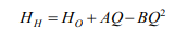
The operating mode of the pump installation is determined by the joint operation of the pump and the pipeline and it can be determined by analytical or graphical solution of the system of equations for the pressure characteristic of the pump and pressure characteristic of the pipeline. The intersection point of characteristics (point A) (Fig. 2.1) determines the operating mode of the pumping unit 17. It also provides the pump efficiency curve and the allowable vacuum suction height HB .
Figure 2.1 - Characteristics of a centrifugal pump unit
The operating mode of the centrifugal pump must satisfy the condition of cavitation-free operation HBC ≤ HBp . In this complex of water injection to ensure stable operation of the pumping unit beskavitatsionoy η is necessary to maintain the desired water level in the ηF .
The control of the pumping unit should be carried out within the zone of its industrial use – QPmin < QP < QPmax.
Taking into account the above analysis of the features of the water injection complex in a roller mill, a diagram is obtained (Figure 2.2) of the main control channels, disturbances and the relationship of parameters in the facility, which is a combination of the main technological elements – a tank with water, a pumping unit and a vertical roller mill.
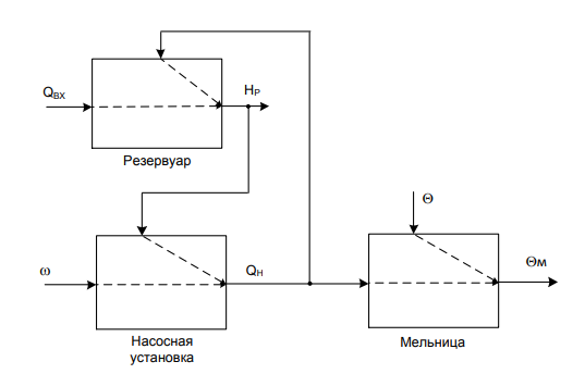
Figure 2.2 - Generalized diagram of the complex of water injection as a control object
The controlled variables characterizing the process of water injection into the mill are (Fig. 2.2):
- for the reservoir - the water level in the reservoir HP;
- for a pump installation - supply at the pump outlet QH;
- vertical roller mill - the temperature at the output QM.
The control actions, allowing necessary to change the mode of operation of the water injection complex, are (Fig. 2.2):
- for the tank - the flow rate of water at the inlet to the tank QBX, which is determined by the position (angle of rotation) of the valve on the supply pipe;
- for a pump installation - pump shaft speed ω;
- vertical roller mill - Water Consumption by injection QH .
The disturbing effects for the elements of the water injection complex are (Fig. 2.1):
- the required flow rate of water for injection QH (for the tank);
- support at the inlet to the pump, depending on the water level in the tank ηP (for a pump installation);
- factors causing a change in temperature at the mill outlet Q (for a roller mill).
Thus, the above analysis of the functioning of the complex of water injection into a vertical roller mill made it possible to formulate the required monitoring and control functions of the developed self-propelled guns:
- monitoring the water level in the tank;
- flow control at the outlet of the pumping unit;
- temperature control at the outlet of the roller mill;
- automatic control of the water level in the tank;
- automatic pump flow control;
- automatic temperature control at the outlet of the roller mill.
3. Analysis of existing solutions
At the moment there is no unified, standard, mass-produced automatic control system for the object under consideration – a complex of water injection into a vertical roller mill of a cement production enterprise.
At present, at the Amvrosievsky cement plant Doncement, the functions of monitoring and controlling the technological parameters of the water injection complex in a roller mill are partially implemented 20. These functions are part of the functions of the general process control system of the coal-grinding department, which was introduced at the enterprise in 2010 [2]. Thus, the existing self-propelled guns does not fulfill all the necessary monitoring and control functions and does not provide the required quality of control of the complex of water injection into a vertical roller mill, which reduces the efficiency of this process.
To automate the wet grinding of raw materials, complete units KRS-63K or KRS-63B have been developed, which allow you to automatically control the mill power with solid components and sludge, as well as control the main technological parameters – limestone flow rate, noise frequency at the beginning of the first mill chamber and in the sludge formation zone ( second camera); sludge viscosity; water consumption; speed of rotation of clay mud bucket feeders.
The cattle system provides the possibility of manual remote control of all regulatory mechanisms.
In the wet grinding department of raw materials, in addition, remote control with locking of all the mill drive mechanisms (including lubrication systems), mill loading mechanisms, mechanisms for transporting the finished sludge and the operation of pumps pumping the sludge, as well as returning excess clay sludge to the pool feeders.
The automatic control system for the ball drum mill SAU SHMB is designed to provide centralized control and automatic control of the technological process of grinding coal in ball drums.
ACS SHMB provides the following functions:
- remote automatic control of the volume of coal loading in the rotating drum of the mill, the temperature of the hot air at the mill inlet, the temperature of the dust-air mixture (PVA) after the mill, the pressure drop across the mill, the vacuum in front of the mill;
- remote control of actuators;
- automatic regulation of the performance of the raw coal feeder;
- automatic stabilization of the PVA temperature at the outlet of the mill;
- stabilization of rarefaction of hot air at the entrance to the mill;
- protection of technological equipment for grinding raw coal;
- raw coal feeder shutdown according to the technological parameters;
- raw coal feeder shutdown according to protection signals.
The generalized structural diagram of the self-propelled guns is shown in Figure 3.1.
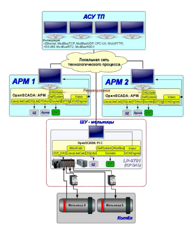
Figure 3.1 - Structural diagram of self-propelled guns
The composition of the self-propelled guns is shown in Fig. 3.1, includes: a PLC control cabinet with a local control touch panel, two automated workstation stations of the operator AWP 1 and AWP 2, and software 22 for integration into the automation system of the workshop (department).
The analysis of the existing solutions discussed above for the automation of the complex of water injection into the vertical roller mill of the production company made it possible to identify the following features, problems and disadvantages.
First of all, it should be noted that in the automation of the main and auxiliary technological processes in the production of cement, individual developments and projects of self-propelled guns, process control systems for a specific process in a particular enterprise are used. As the analysis above shows, in the existing process control systems of cement production enterprises there are no standard, standard, unified automation solutions, including for a water injection complex. This feature is associated with the individuality of technological equipment and technological schemes of the enterprises under consideration [5].
The technical implementation of self-propelled guns by a complex of water injection into a vertical roller mill, as can be seen from the analysis, is made on the basis of components from various manufacturers.
As a rule, the monitoring and control functions of the water injection complex in a roller mill are implemented within the framework of a common automatic process control system with a vertical roller mill (or automatic process control system with a coal-grinding department), and not a separate self-propelled gun. This leads to the fact that the monitoring and control functions of the main parameters are performed, often according to simplified schemes and control principles, which leads to unsatisfactory control quality from the standpoint of modern requirements. In addition, part of the control functions is implemented remotely by the operator in manual mode, including the functions of controlling water injection.
Since Moore automata are an important part of digital systems, the problems of their synthesis, analysis, minimization, and implementation have been widely studied by both American, European, Japanese scientists, and domestic experts. The implementation of digital devices using FPGA and Verilog HDL has also been the subject of a number of works, mainly by Western school researchers.
4. Development of the concept of building self-propelled guns
4.1 Justification of the choice of control method of the pumping unit
The parameters of the operating mode of the pump unit can be controlled in the following ways:
- changing the frequency of rotation of the drive motor using frequency converters;
- changing the characteristics of the network (pressure pipe) using a controlled valve;
- air supply to the suction system of the pump.
Each method of regulation has both its advantages and disadvantages.
The pressure head characteristic of the pump HH (Q) at the rated speed n and the characteristic of the pipeline HTP (Q) determine the operating point of the pump-pipeline system (point 2) in the nominal operating mode (Fig. 4.1).
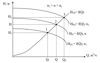
Figure 4.1 - Control of the parameters of the pumping unit by changing the speed of the drive motor
The operating mode of the drainage plant is determined by two main parameters - head H and supply Q. If the speed changes, the pressure characteristic of the pump, the operating point of the drainage plant, and therefore the parameters H and Q, will change (Fig. 4.1). The pressure head characteristics of the pump when changing the frequency from n1 to n2 provide a change in the parameters of the operating mode from (Q1 , H1 ) to (Q2 , H2 ). Points 1, 2, 3 lie on the pressure characteristic of the external network (pipeline) NTP (Q) and determine the operating modes of the pump unit when the speed changes n2 > n > n1.
Controlling the parameters of the pumping unit by changing the rotational speed of the drive motor has the following advantages: versatility, the ability to achieve pump feeds of both smaller and larger nominal; profitability – energy consumption for management is determined by efficiency devices used to change the speed. C.p.d. with the right selection can be quite high [4]. The disadvantages include the relatively high cost of a controlled electric drive.
A lot of research is devoted to controlling the operating parameters of a pump by supplying air to its suction system. The attitude of researchers to this method of management is ambiguous. At the initial stages of research, this method was considered promising and economical: low power consumption for control, relatively large depth of feed change. However, further studies have shown that suction and air entering the suction system of the pump adversely affects its operation. The disadvantages of this control method: the ability to control only to reduce the flow, the possibility of disruption of the pump at high air flow, a complex control system. Air leaks cause a sharp deterioration in acoustic and vibrational characteristics, pressure pulsation, supply, power, pressure at the inlet [6]. Particularly negative air ingress affects the durability and reliability of the hydraulic 26 discharge device of a centrifugal pump unit. Given all these factors, it should be recognized that the method of controlling the parameters of the pump installation by the air intake is unacceptable.
The control of the operating mode of the pump installation can be carried out by changing the pressure characteristic of the network with a constant characteristic of the pump. The most used practical implementation of this control method is the throttling of the discharge pipeline by a controlled valve (Fig. 4.2).
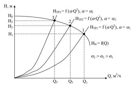
Figure 4.2 - Control of the parameters of the pumping unit by changing the pressure characteristics of the pipeline
By closing or opening a controlled valve, we change the network resistance α × Q2 (Fig. 4.2), as a result of which the pressure characteristic of the pipeline changes [1]. The slope of the pressure characteristic of the NTR pipe is determined by the pipe resistance α. The more the controlled valve is covered, the greater the resistance of the pipeline (α3 > α2 > α1 ), and the steeper the network characteristic (Fig. 4.2). Changing the characteristics of the pipeline (HTP1 → HTP2 → HTP3 ) leads to a change in the operating mode of the centrifugal pump installation (Fig. 4.2).
The advantages of this control method are as follows: simplicity, reliability, lack of need for expensive equipment. The disadvantage of this method is the increase in specific energy consumption for the process of water injection.
Thus, when developing a model of the control object and constructing an automatic control system for the water injection complex in a vertical roller mill, it is necessary to take into account the possibility of using two control methods – changing the speed of the drive electric motor (when the pump starts and stops on a closed valve, as well as controlling the pump flow when to stabilize the set temperature at the outlet of the mill) and throttle the discharge pipe with a controlled valve – with a smooth opening / s closing the valve after starting the pump to a closed valve [7].
4.2 Justification of the choice and expected results of the selected version of the ACS concept
The implementation of the developed self-propelled guns with a complex of water injection into a vertical roller mill (Fig. 4.3) is proposed according to the feedback principle for the main controlled variables for each technological module:
- the water level in the tank NP;
- pump output QH
- an outlet temperature of the vertical roller mill θM.
ACS reservoir (Fig. 4.3) is implemented according to the feedback principle – the required water level in the reservoir HP maintained by changing the flow rate of water QBX supplied to the reservoir. Perturbing influence in ACS reservoir is flow of water consumed from the reservoir, which in this complex water injection is applied to the output of the pump device QH.
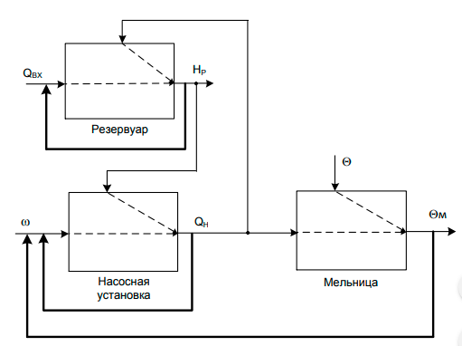
Figure 4.3 - Structural diagram of the concept of building self-propelled guns
The self-propelled guns at the outlet temperature of the roller mill are implemented according to a two-loop scheme of subordinate regulation with the inclusion of the elements of two technological modules – a pumping unit and a mill (Fig. 4.3). The internal control loop stabilizes the required flow rate at the output of the pumping unit QH by changing the frequency of rotation of the pump shaft ω [3]. The external control loop sets the required water flow to the mill (equal to the supply at the pumping unit output QH ) to maintain a given temperature θM at the mill outlet under the influence of temperature disturbances θ (Fig. 4.3).
Using the proposed concept for the development of self-propelled guns with a water injection system allows to improve the quality indicators of maintaining the considered technological parameters – the water level in the tank, the supply at the outlet of the pump unit, the temperature at the outlet of the roller mill; exclude the occurrence of fluctuations in the above parameters to increase reliability and reduce operating costs for the control object under consideration – a complex of water injection into a vertical roller mill.
Figure 4.4 - Scheme of operation of a vertical roller mill
(animation: 8 frames, 5 reps, 21 kilobytes)
Conclusions
The analysis of existing solutions in the field of automation of the complex of water injection into a roller mill confirmed the relevance of this topic and the need to develop a modern automatic control system for this facility.
The concept of developing a system for automatic control of a complex of water injection into a vertical roller mill is proposed. Based on the analysis of the existing principles for the construction of automatic control systems, it was decided to use the feedback principle as the most suitable for solving the task of automation of the object in question. Implementation of the proposed concept will increase reliability and reduce operating costs for the operation of the complex of water injection into a vertical roller mill
Список источников
- Гаврилов, П. Д. Автоматизация производственных процессов. Учебник для вузов. / Гаврилов П. Д., Гимельштейн Л. Я., Медведев А. Е. – М.: Недра, 1985. - 215 с.
- Черкасский, В. М. Насосы, вентиляторы, компрессоры. / В. М. Черкасский – М.: Энергоатомиздат, 1984 - 416 с.
- Локалов, Г. А. Осевые и центробежные насосы тепловых электрических станций. / Г. А. Локалов, В. М. Марковский – Екатеринбург: Изд-во Урал. ун-та, 2016 - 140 с.
- Карелин, В. Я. Насосы и насосные станции: Учеб. для вузов / В. Я. Карелин, А. В. Минаев - 2-е изд., перераб и доп. - М.: Стройиздат, 1986. - 320 с.
- Гейер, В. Г. Шахтные вентиляторные и водоотливные установки. / В. Гейер, Г. Тимошенко. – М.: Недра, 1987.- 270 с.
- Строй-Техника.ру. Строительные машины и оборудование, справочник. Автоматизация процессов помола. [Электронный ресурс]. – Режим доступа: http://stroy-technics.ru/article/avtomatizatsiya-protsessov-pomola.
- OpenSCADA. Система автоматического управления загрузкой шаровых барабанных мельниц. [Электронный ресурс]. – Режим доступа: http://oscada.org/ru/glavnaja/produkty/odinochnaja-stranica/article/the-automaticcontrol-system-acs-of-the-ball-mills-load/ .