
Abstract
Содержание
- Introduction
- 1. Theme urgency
- 2. Goal and tasks of the research
- 3. Types of robotic mechanisms
- 3.1 Robots with a serial kinematic structure
- 3.2 Robots with parallel kinematic structure
- Conclusion
- References
Introduction
Currently, one of the main tasks of electromechanical systems is the positioning of a certain mechanism. A system that allows you to independently control the movement of several degrees of freedom at the same time is called a robot. The degree of freedom is the possible trajectories of translational or rotational motion.
At the moment, the most common type of robotic systems are robots with sequential kinematics. These are traditional systems in which the links are connected in series. This type of system has a number of disadvantages, so their use is impractical for a wide range of technological tasks.
The second type of robotic systems is robots with parallel kinematics. In these systems, the drive devices are connected in parallel and are independent of each other. These systems are not characterized by the disadvantages of systems with sequential kinematics, so their use in individual tasks is more appropriate.
1. Theme urgency
Despite the widespread use of classical robotic systems with sequential kinematics, robots with parallel kinematics are much more suitable for many tasks. The relevance of the work is due to the fact that many tasks require extremely high accuracy of working out the positioning task. At the same time, the requirements for positioning accuracy are growing every year. Therefore, it is extremely important that the system fulfills the task with as little error as possible. The master's thesis is devoted to the study of robotic systems with parallel kinematics and the development of a control system on the example of the Biglide robotic mechanism.
2. Goal of the research
The goal of the study is to develop a control system for a robotic complex with parallel kinematics in order to increase the accuracy of positioning.
The object of the study is the Biglide robotic mechanism.
3. Types of robotic mechanisms
3.1 Robots with a serial kinematic structure
<The most common today is a class of manipulators with expressed anthropomorphic kinematics, clearly resembling the structure of the human hand. Such mechanisms consist of serially articulated links, each of which controls one degree of freedom of the working body, and are called robots with serial kinematics (serial robots). This kinematic structure allows you to control n degrees of freedom of the working body, provided that n links are driven [1].
A classic example of a mechanism with serial kinematics is a manipulator operating in a spherical coordinate system(spherical robot), all links of which are connected by means of hinges, and having, as a rule, six degrees of freedom (Figure 3.1). Another common example is the Scara manipulator (Figure 3.2), which allows you to control the four degrees of freedom of the actuator.
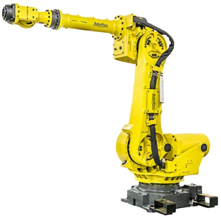
Figure 3.1 – Machine-type manipulator
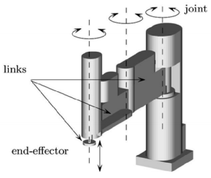
Рисунок 3.2 – Manipulator of the Scara type
The first thing you should pay attention to is the interrelation of the robot's load capacity and its own weight. For manipulators of the articulated type (at the current time) this indicator does not exceed 0.15. Thus, in order for the robot to lift a load weighing 0.5 tons, its own mass, at the same time, must reach at least 3330 kg. For manipulators of the Scara type, this indicator is slightly better, especially for so-called direct-drive robots (direct-drive robots), which do not have a gearbox in the kinematic chain. However, at the moment, it does not exceed 0.25. Thus, in order for a Scara-type manipulator to have a load capacity of 0.5 tons, it itself, at the same time, must have a mass of at least 2000 kg.
Another important detail concerns the positioning accuracy, for estimating which there are two different indicators: the absolute accuracy and stability of positioning. The absolute error characterizes the difference between the specified position of the working body and its actual position, which will be reached after the end of the positioning process. Positioning stability, in turn, is defined as the maximum distance between the two final positions of the working body, which it has adopted after exercise the same movement task, but under different initial conditions. In the reference literature, the manufacturer usually provides data concerning the stability of the positioning of the working body. The stability of positioning of this type of mechanisms may be unsatisfactory for solving some problems, while the absolute error, in most cases, is much worse, due to the following factors:
- the limited accuracy of the sensors;
- the presence of a gap in the engine;
- the final rigidity of the links and, as a result, the appearance of bends in them;
- insufficient quality of the geometric implementation.
Since each of the links of such a manipulator must, in addition to the weight of the payload, also support the next link, they all eventually experience a significant impact of bending moments, to compensate for which the links of the kinematic chain are given additional rigidity, which leads to a weighting of the entire mechanism. A significant mass of components and parts, in turn, leads to the fact that, when moving at high speeds, the mechanism begins to experience the impact of centrifugal and Coriolis forces, which complicates the control of the manipulator.
Elastic deformations also affect the positioning accuracy, and they cannot be measured and therefore cannot be compensated for. Moreover, the links of a serial kinematic chain tend to increase the positioning error: a completely insignificant, at first glance, measurement error in the first or second link of the chain can lead to a significant positioning error of the working body.
Based on the above, we can say that the use of robots with serial kinematics is impractical for tasks that require manipulations with objects of large mass, or high positioning accuracy.
3.2 Robots with parallel kinematic structure
A robot with parallel kinematics (parallel robot) generally consists of a working body with n degrees of freedom and a fixed base connected by n independent kinematic chains.
A classic example of this type of manipulator is the mechanism designed in 1955 by engineer V. E. Gough and proposed by D. Stewart in 1965 as the basis for building flight simulators, and named after the latter, the Stewart platform (Figure 3.3). The movable element of this mechanism is a hexagonal platform, each of the vertices of which is attached to the movable rod by means of a ball joint. Another end of the rod is attached by means of a cardan joint to the fixed base. The linear actuator allows to change the length of the rod, thereby setting the position for the platform. In total, the mechanism involves six linear actuators.
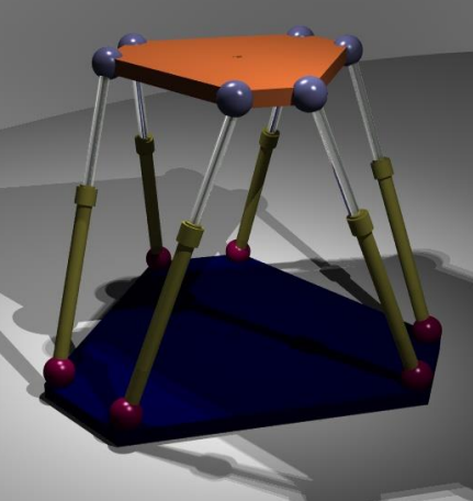
Figure 3.3 – Model of the Stewart platform
Let's consider the main advantages of parallel kinematics in comparison with serial kinematics using the example of the Stewart platform. The most obvious advantage is a more favorable correlation of the load capacity of the mechanism to its own weight. This is due to the fact that the load is distributed evenly across all the sliding cylinders and, in the case when the platform occupies a central position, stands 1/6 of the total load. In addition, the elastic deformations in the sliding cylinders are very small. These two factors make it possible to significantly reduce the weight of the mechanism by using a lower power drive and smaller links. Another important advantage of parallel kinematics is the increased positioning accuracy, for which there are two reasons:
- elastic deformations (not measurable) in the kinematic chain links are minimized;
- the measurement error of the internal sensors of the manipulator slightly affects the positioning error (for example, if the measurement error of all sensors is the same, the positioning error will occur only on the vertical axis and will be comparable in magnitude to the measurement error).
The advantages of parallel mechanisms described above have determined their application areas. So the Stewart platform is widely used [2]:
- in the construction of air exercise machines and other highly dynamic simulation stands;
- for positioning mirrors of large radio telescopes (Fig. 3.4);
- in medicine (the so-called Taylor spatial frame);
- in spacecraft docking systems (Low Impact Docking System-LIDS)
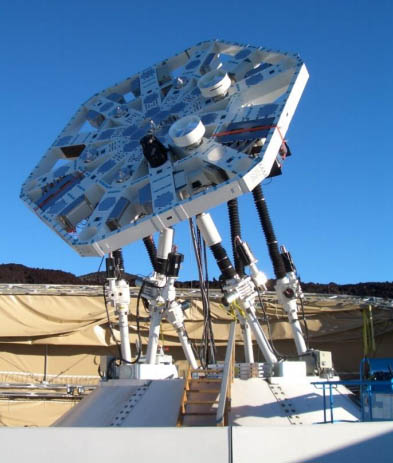
Figure 3.4 – A mechanism with parallel kinematics that performs the positioning of a radio telescope
In this work, we will use the simplest parallel mechanism with two degrees of mobility based on linear actuators (biglide mechanism) [4], whose kinematic scheme is shown in the figure 3.5.
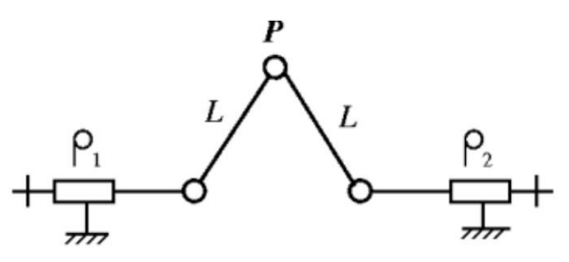
Figure 3.5 – Kinematic scheme of the mechanism Biglid
The input for this mechanical system is the velocity vector of linear actuators ρ, and the output is the velocity vector of the working body t, which are described by expressions, respectively (3.1) and (3.2):
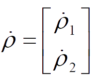 |
(3.1) |
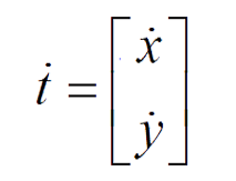 |
(3.2) |
The relation between the vectors ρ, and t is described by the formula (3.3):
 |
(3.3) |
For the Biglide mechanism, as for most mechanisms with a parallel kinematic structure, the matrices A and B are non-constant and depend on many factors, in particular on the position of the executive body P in the working space and even on the direction of movement of the executive body in the Cartesian coordinate system. Accordingly, the dynamics of the positioning process will change. This property of parallel mechanisms is a significant disadvantage, especially in the context of industrial applications.
The mechanism under study has two special states, the so-called singularity points, which must be taken into account during operation. The first special state occurs when the determinant of the matrix A tends to zero and is called a parallel singularity (Figure 3.6). The occurrence of this condition is highly undesirable, since it entails a loss of controllability of the working body P and can lead to damage to the mechanism.
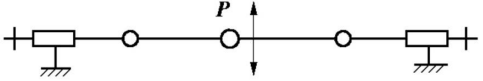
Figure 3.6 – The point of the parallel singularity of the mechanism
The second type of special state occurs when the determinant of the matrix B rushes to zero. This position of the mechanism is called a serial singularity (Figure 3.7). This state is characterized by the fact that there is a certain direction of movement in it, along which the speed applied to the executive body P will always be zero. In the case of the mechanism under consideration, the point of the serial singularity coincides with the upper boundary of the working area, which is shown in figure 3.8.
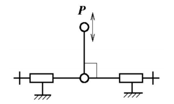
Figure 3.7 – The point of serial singularity of the Biglide mechanism
Figure 3.8 – The workspace of the Biglide mechanism. Animation: 8 frames, 7 cycles of repeating, 24,2 kB
Conclusion
In the course of the work, robotic mechanisms with serial and parallel kinematics were studied. Their parameters, advantages and disadvantages were compared.
The main disadvantages of robots with serial kinematics (serial robot)these include low load capacity in relation to the mass of the device, as well as relatively low positioning accuracy due to the limited accuracy of the sensors, the presence of a gap in the engine, the final rigidity of the links and, as a result, the appearance of bends in them, insufficient quality of the geometric implementation and the presence of elastic deformations that are not possible to calculate, and therefore, compensate. All of the above makes the use of this type of robot impractical for solving a number of tasks that require high accuracy and speed of positioning (see point 3.1).
Robotic mechanisms with parallel kinematics (parallel robot) have a number of advantages in comparison with robots with serial kinematics. These include a high load capacity in relation to the weight, which is due to the fact that the load is distributed evenly between the mechanisms. Also, the advantages of robots with parallel kinematics include high positioning accuracy. It is due to the fact that elastic deformations in the mechanism are minimized, as well as to the fact that the measurement error of internal sensors only slightly affects the final positioning accuracy, unlike robots with serial kinematics (see point 3.2).
This master's work is not completed yet. Final completion: December 2011. The full text of the work and materials on the topic can be obtained from the author or his head after this date.
References
- Merlet J.-P. Parallel Robots – Dordrecht: Springer, 2006. – 394 p.
- Зуев С.М. Стабилизация положений равновесия нагруженных модификаций платформы Стюарта: дис. канд. физ.-мат. наук: 01.02.01 – СПбГУ, СПб, 2014 – 115 с.
- Bonev I. Delta Parallel Robot – The Story of Success [Электронный ресурс] // ParalleMIC – The Parallel Mechanisms Information Center, 2001. URL: http://www.parallemic.org.
- Majou F., Wenger P., Chablat D. A Novel Method for the Design of 2-dof Parallel Mechanisms for Machining Applications – IRCCyN, Nantes, 2007 – 10 p.
- Старостін С.С., Сафонов А.П. Позиційне управління робототехнічним пристроєм із замкненою кінематикою // Вісник Кременчуцького державного університету. – Кременчук, 2010.
- DS1103 PPC Controller Board: Feature Reference. – Paderborn: dSpace GmbH, 2001 – 112 p.
- E210-VF User Manual 2.2. – Spreitenbach: NTI AG, 2005 – 49 p.
- Industrielle Linearmotoren. Produktkatalog: Ausgabe 16 – Spreitenbach: NTI AG, 2005 – 580 p.