
Investigation of the influence of the destroyed object position relative to the extreme support of the excavator on the efficiency of the hydraulic hammer working process
Content
- Introduction
- 1. Theme urgency
- 2. Goal and tasks of the research
- 3. Research and Development Review
- 3.1 Overview of the issue status
- 3.2 Operating conditions and rules for pressing the hydraulic hammer to the material being destroyed
- 3.3 Influence of the position of the destroyed material relative to the extreme support of the excavator on the efficiency of the hydraulic hammer working process
- Conclusion
- References
- 3.3 Influence of the position of the destroyed material relative to the extreme support of the excavator on the efficiency of the hydraulic hammer working process
Introduction
Hydraulic demolition hammers are widely used for demolition of building materials, rocks and strong soils. Experience in operating shock-acting machines shows their high efficiency in reconstruction and demolition of construction sites, construction of transport highways, tunnels, preparation of construction sites, etc. At present, there are various designs of impact action devices, among which the most common are pneumatic-hydraulic and hydraulic devices, which include hydraulic breakers. In this case, the results of several studies indicate that hydraulic shock devices provide a relatively high efficiency.[1, 2].
1. Theme urgency
The wide spread of hydraulic hammers is limited by the use of simplified calculation methods that do not fully take into account
the peculiarities of the working process of the excavator-hammers
system and some parameters that affect the efficiency of work.
Analysis of works in which the solution of this problem has been started and on which the author relies, highlighting the parts of the general problem that were not solved earlier - to which the article is devoted.
2. Goal and tasks of the research
The purpose of this work is to estimate the dynamic parameters ensuring the effective destruction of the material, the system of excavator-hydraulic hammer
taking into account the possible positions of the destroyed object.
To achieve this goal, the following tasks were set and solved: the development of a calculation scheme of the dynamic system of excavator-hydraulic hammer
; the development of a mathematical model of the hydraulic hammer working process;
obtaining the calculated dependencies for the determination of the forces arising in the structural elements; determining the influence of the position of the destroyed object relative to the extreme support of the excavator on the efficiency of the hydraulic hammer working process.
To consider the relevance and advantages of applying innovative developments hammers; set the need for proper fit of the tool hammer to destroy the surface of; to make recommendations when operating the breaker.
3. Research and Development Review
3.1 Overview of the issue status
The range of impact energy of modern water hammer machines, depending on technical operations, is quite wide and ranges from 200 to 30,000 j at frequencies from 4 to 100 Hz [11, 12, 25]. Hydro-and pneumatic impact mechanisms can improve the efficiency of work related to the destruction of foundations, frozen ground, asphalt concrete surfaces, etc.
Hydraulic drive in impact machines provides higher efficiency, relatively high durability, which is due to the presence of constant lubrication between the friction surfaces and low air pollution in the working area. The presence of a hydraulic drive makes it possible to regulate the energy and frequency of impacts of the hydraulic pulse unit within a wide range. In recent years, there have been significant changes in the structure of construction works. The change in the nomenclature and scope of work is caused by a decrease in the share of large-scale construction and a reorientation to earthworks that serve the construction of low-rise buildings [16, 17]. The increase in the number of emergency and repair and restoration works in recent years is caused by high wear and tear of the state of public utilities, which makes it necessary to perform a large amount of work such as the destruction of frozen ground during the repair of heating systems in winter. A characteristic feature of these works is the distribution of objects, the specifics of their implementation: small volume, cramped conditions of dense urban development. This requires mobile and inexpensive excavators that have a sufficiently powerful power plant to drive hydraulic equipment [18, 19]. Currently, the destruction of materials is carried out by outdated domestic serial hydro-pneumatic hammers, which have low efficiency and are significantly inferior to foreign analogues. This equipment does not always meet modern requirements for efficiency and vibration safety [20, 26]. Existing hydraulic hammers require modernization based on scientific recommendations for the development of a new generation of water hammer mechanisms. One of the advantages of implementing shock systems may be that the striking body and the object being destroyed can be separated in the technological space. For the transmission of energy by longitudinal impact used a rod system, whose effectiveness depends on knowledge about what is happening in a dynamic system processes. Both domestic and foreign scientists were engaged in the problems of longitudinal impacts. The conducted research shows that the processes occurring in the system can be successfully described by the wave model of a longitudinal impact. Crushing of oversized materials can be realized both by means of an explosion and by mechanical destruction under the influence of shock loads that cause destruction of internal connections in the object [21]. Currently, there are a large number of types of impact mechanisms on the market. Economic expediency has led to the spread of machines that implement a mechanical method of destruction. Hydraulic hammers are complex products that require quality of production and manufacture, strict compliance with the rules of technical operation. An alternative to hydro- and pneumatic hammers can be electromagnetic strikers that implement pulse loads with an impact energy of up to 30 kJ [22,23, 24]. The operation of these devices is provided by converting the electrical energy stored in the capacitor Bank into the mechanical energy of the mobile striker. Their advantages are simplicity, less weight and cost.
3.2 Operating conditions and rules for pressing the hydraulic hammer to the material being destroyed
Figure 1 – Pressing the hydraulic hammer to the material being destroyed
(animation:38 frames, 12 repetition cycles, 221 kilobytes)
The hydraulic hammer is an active device, and the impact force affects not only the material being destroyed, but also the base machine, which is experiencing significant loads.
This influence is extinguished by the mass of the hydraulic hammer itself, the mass of the handle, boom, and part of the mass of the machine itself.
To balance and minimize the reactive forces that occur during operation, it is necessary to press the tool firmly against the material being destroyed strictly perpendicular to its surface.
This is due to the hydraulic cylinders of the boom and suspension, the weight of the excavator itself, which is suspended
on an additional support point (which is the hydraulic hammer).
At the same time, part of its chassis is detached from the ground. Naturally, it is very difficult to achieve a complete coincidence of the axis of movement of the working tool and the axis of pressing, especially taking into account that when the tool is deepened into the rock, this angle changes.
But it is necessary to strive for this, because if these axes do not match, the wear of the guide bushings and vibration loads on the base machine significantly increase, as well as the efficiency of work decreases [27].
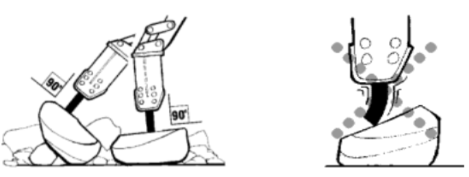
Figure 2 – View of hydraulic hammer installation
In addition, installing the hydraulic hammer at an angle to the surface to be processed significantly increases the risk of tool slipping, which often threatens to break (Fig. 2)
Given the fact that it is almost impossible to install the hammer strictly perpendicular to the surface, it is impossible to completely exclude radial loads.
In addition, dust and material particles always get into the gap between the guide bushings and the working tool, which, acting as an abrasive, significantly reduce the service life of the hydraulic hammer.
To reduce these negative impacts, the tool-bushing
pair must be thoroughly lubricated, and the lubricant must be regularly updated during operation.
New grease is introduced through the oil press, which is installed in the tool box. If there is insufficient lubrication, friction between the working parts leads to contact welding, as well as the appearance of potholes and burrs.
The latter become foci of fatigue cracks that destroy the tool. It is worth noting that rusty metal is much more susceptible to fatigue, which means that the tool must be stored in a well-oiled state.
For a tight fit of the tool to the processed material, it is necessary to hang out
the excavator.
In this case, the body of the excavator seems to fall from a height, striking the stationary tool, repeatedly increasing the force of the impact.
Studies have shown that dynamic loads that occur when an excavator falls from a height of more than 15 cm can lead to serious damage to the chassis of the machine.
To reduce the risk of such breakdowns, it is forbidden to hang the excavator more than 15 cm.
In addition, manufacturers, in an effort to reduce the impact on the base machine, equip hydraulic hammers with elastic shock absorbers that absorb some of the energy. But their effectiveness is relatively low and they are still unable to protect the car from damage received when falling from a height of more than 15 cm. Hydraulic cylinders of the hydraulic hammer drive also serve as shock absorbers, but only when they do not reach the extreme position (so when the rod rests on the bottom of the sleeve) by at least 10 cm. In this case, the working fluid acts as a hydraulic shock absorber.
If the processed material is not destroyed in 15-30 seconds of operation of the hydraulic hammer, then it is necessary to move the tool to a new point, usually closer to the edge.
This manipulation will increase productivity and also save the working tool. The fact is that when you work in one place for a long time, the tool gets hot.
It is necessary to rearrange the tool after turning it off, because the main parts are exposed to increased wear at idle
. There are models equipped with idling blockers (hitchhiking
system), i. e. the hydraulic hammer automatically switches off when there is no load.
During operation, the tool-bushing
pair gradually wears out, resulting in a gap between the tool shank and the guide bushing gradually growing.
This value must be regularly monitored and if the gap increases by more than 5% of the tool's landing diameter, the entire pair must be changed. Otherwise, the hammer head of the hydraulic hammer will strike at the edges of the end of the tool, which are cracked, multiply the destruction process.
There are models that use working tools with spherical shank heads. In these cases, when the tool center is deflected within the limits of the sleeve wear, the point of contact between the striker and the tool deviates slightly from the center, which reduces the probability of damage.
But this design still does not relieve you from the need to control the gap and replace worn parts in a timely manner.
In most cases, hydraulic hammers are equipped with a whole set of working tools, each of which is most effective for a certain type of material. So the flat chisel is most effective when working with soft materials (concrete, including reinforced), asphalt pavement, frozen soils and brickwork. A conical or pyramidal peak is optimal when crushing high-strength materials, such as unreinforced monolithic or slightly cracked concrete, or preliminary destruction of reinforced concrete structures. And finally, a tool with a blunt end is best suited for destroying oversized crystalline rocks (granite, magma). When working with such a tool, it is recommended to smoothly deviate it from the front axis, but not more than 5 degrees. In this case, the colored rock is removed from under the blunt end of the tool and the impact efficiency increases. Ramming is used for compaction of loose soil.
In addition, to work with different materials, it is necessary to select such characteristics as the strength and frequency of impacts. The higher the density of the material, the greater the force needed to break it. Conversely, for the destruction of thin ceilings, the frequency of strikes comes to the fore. Switching modes allows for more efficient use of equipment in various operating conditions [28, 29].
3.3 Influence of the position of the destroyed material relative to the extreme support of the excavator on the efficiency of the hydraulic hammer working process
The computational scheme for the mathematical model output is given in Fig. 3. This computational scheme is described by the system of differential equations:
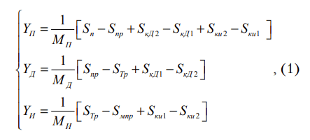
where YП,YД,YИ – coordinates of excavator suspension, hydraulic hammer striker and hydraulic hammer working device respectively.
With the help of differential equations on the basis of calculation scheme with basic parameters of EK-14 excavator and FINE-6BL hydraulic hammer manufactured by Feel Industrial Engineering Co., ltd
(Yu. Korea) a mathematical model of working cycle was built.
With the use of the developed mathematical model, a computational experiment was carried out, as a result of which diagrams of forces (Fig. 4) were drawn: applied to the material being destroyed; in the wedge stroke limiters; in the striker stroke limiters; in the excavator suspension. The simulation time was 2 seconds.
Let's consider each of the diagrams to determine the main parameters of the array destruction and to analyze the hydromolot operation process.
The amplitude of the impact force on the material being destroyed is in the range of 0 N to 106 Н. The main operating value of the effort is 6 · 105 Н and has a period of 0.25 sec.
The excavator suspension force diagram clearly shows a 0.25 sec transition process caused by the first contact of the striker with the array. After the transition
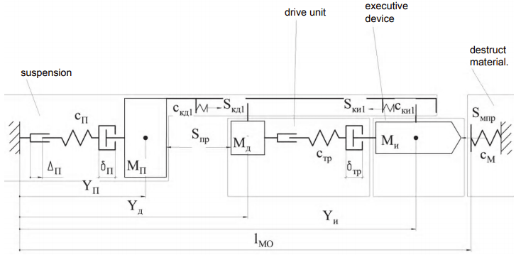
Figure 3 – Calculation scheme of excavator-hydromolot
system
СП, δП, ΔП – stiffness, coefficient of resistance to movement and offset of excavator suspension, respectively; lмо – current coordinate of the hydromolot;
SкД1, Sки1, Sп, Sпр, Sмпр – efforts in the rear stop of the striker, in the rear stop of the wedge, in the suspension of the excavator, which sets the striker in motion and pressing the hammer to the material to be destroyed, respectively;
МП, МД, МИ – given weight of excavator, striker and hydraulic hammer wedge respectively; δТР, δП – clearance in the striker-wedge connection and in the suspension of the base machine, respectively;
СТР, СТР1, СКД, СМ – the coefficients of stiffness of the striker, the limiter of the striker stroke and at the contact of the working body with the destroyed material respectively.
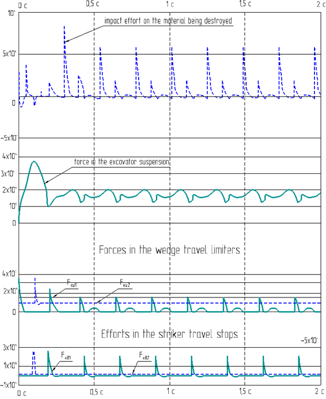
Figure 4 – Hydromolot and excavator workflow diagrams
process is complete, the excavator suspension forces become intermittent with an oscillation amplitude of 2 · 104 Н, The increase in suspension force occurs after strikes of the striker and the wedge.
The force diagram for the wedge travel stops represents the forces of the two stops. Since in these calculations the presence of a front stop was not provided, its rigidity was taken to be zero and the destructible material played the role of this limiter (straight line in the diagram)
The rear stop is a spring that absorbs the impact when the wedge moves backwards. The force in this stopper is about 3 · 105 Н, and the period of its oscillation corresponds to the period of the striker movement.
The last diagram describes the forces in the striker stroke limiters. As in the previous diagram, a wedge acts as the front stop. The amplitude of the force is 2 · 105 Н
Investigation of the impact of the position of the destroyed object on the extreme support of the excavator
With the use of the developed mathematical model (3) researches of influence of position of destroyed object concerning extreme support of excavator on efficiency of working process of hydraulic hammer which was estimated by efforts of influence of hydraulic hammer on a material at breakage and efforts in excavator suspension have been conducted.
The study of the influence of the reduced mass on the hydromolot efficiency was carried out for two positions of the mountain massif relative to the excavator: at the maximum distance – 5 m and at the minimum distance – 2 m.
The simulation was carried out in the range of changes in the reduced weight of the excavator from +100% to -50% of the nominal values. The graph of the influence of the reduced mass on the efforts impact of the hydraulic hammer on the material being destroyed is shown in Fig. 5.
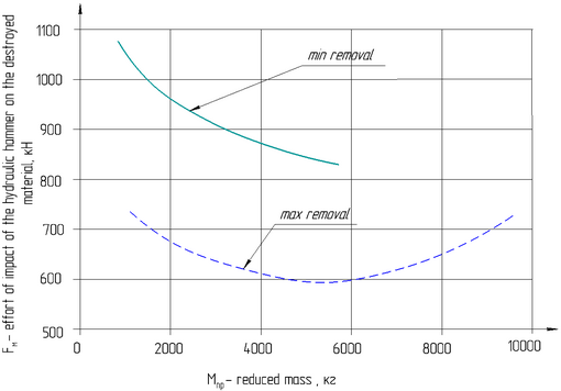
Figure 5 – The graph of dependence of force of influence of a hydromolot on the destroyed material on the reduced mass.
The analysis of this graph allows us to conclude that the destruction near the excavator is more effective than at the maximum distance from it for all values of its reduced mass. At the same time, the hydraulic hammer force on the material being destroyed near the excavator is 850…1080 kN, and at maximum distance of 600…740 kN. Consequently, at minimum distance from the destroyed object (2 m) destruction efficiency is one and a half times or two times higher in comparison with maximum distance (5 m).
Dependence of force in excavator suspension on its reduced mass is shown in the figure. 6.
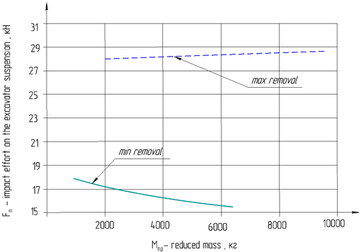
Figure 6 – The graph of force dependence in the excavator suspension on its reduced mass.
As can be seen from the graph, at different values of the excavator weight given, the forces in its suspension vary within the range of 15…29 kN. At maximum removal of destroyed object the range of force change in its suspension is 1 kN. This allows us to conclude that at the maximum extension of the attachment equipment (boom and hydraulic hammer handle) the value of the reduced mass of the excavator practically does not affect the forces in its suspension, they are maximum for the entire measurement range. Working in this mode leads to high loads on the elements of the excavator design and is not rational. Accordingly, at the minimum distance of the hydraulic hammer from the excavator, the suspension forces are minimal and range from 15 kN to 18 kN.
Conclusion
Thus, the position of the destroyed object relative to the extreme support of the excavator has a significant impact on the efficiency of the hydraulic hammer working process. Minimum removal of the destroyed object allows to realize almost in one and a half or two times greater forces of influence on the destroyed material with minimum efforts in the excavator suspension.
The question of the need for the use and operation of hydraulic hammers is considered. Recommendations are given and rules of operation of the hydraulic hammer when pressing it to the destroyed material are established.
When writing this essay, the master's work is not yet complete. Final completion: June 2021. The full text of the work and materials on the topic can be obtained from the author or his supervisor after the specified date.
References
- Галдин Н. С. Основы теории многоцелевых гидроударных рабочих органов дорожностроительных машин [Текст]: дис… д-ра техн. наук: 05.05.04 / Галдин Николай Семенович. – Омск, 2000. – 325 с.
- Лепешкин А. В. Гидравлические и пневматические системы [Текст]: учебник / А. В. Лепешкин, А. А. Михайлин; под ред. Ю. А. Беленкова. – М.: Издательский центр
Академия
, 2004. – 336 с. - Глотов Б. Н. Проектирование, изготовление и испытание опытных образцов ручных гидромолотков [Текст] / Б. Н. Глотов: материалы II международ. науч. симп. (21–23 октября 2003 г., Орел). – Орел: ГТУ, 2003. С. 492–493.
- Горин А. В. Экспериментальные исследования гидромолотов с высокой энергией удара [Текст] /А. В. Горин, Д .А. Юрьев, С. Н. Семенюк // Механизмы и машины ударного, периодического ивибрационного действия: материалы Международного науч. симп. (17–19 октября 2000 г., Орел). – Орел: ГТУ, 2000. С. 128–130.
- Жуков И. А. Развитие научных основ повышения эффективности ударных машин для бурения скважин в горных породах [Текст]: автореф. дис… д-ра техн. наук. / И. А. Жуков. – Новосибирск, 2017. – 39 с.
- Климов В. Е. Разработка функциональной схемы процесса построения критериальных уравнений для создания математической модели разрушения минеральных сред ударным инструментом [Текст] / В. Е. Климов // Ударновибрационныесистемы и машины для строительной и горной отраслей: материалы VI Междунар. научн. симпозиума (25–26 апреля 2017 г., Орел). – Орел: ОГУ им. И. С. Тургенева, 2017. С. 121–127.
- Лагунова Ю.А. Специфические особенностиэксплуатации механизмов ударного действия [Текст] / Ю. А. Лагунова, А. А. Митусов, О. С. Решетникова //
Горная и нефтяная электромеханика – 2016
: матлы III Междунар. научнопракт. конф. (10–13 октября 2016 г.,Пермь). – Пермь: ПНИПУ, 2016. С. 72–75. - Митусов А. А. Анализ КПД гидравлических молотов горных машин [Текст] / А. А .Митусов //Горный журнал. 2006. № 10. С. 74–76.
- Митусов А. А. Исследование процесса раскрытия двухлинейного клапана в фазе рабочего хода гидромолота [Текст] / А. А. Митусов, Ю. А. Лагунова, О. С. Решетникова // Горное оборудование и электромеханика. 2017. № 2. С .34–40.
- Митусов А. А. Анализ параметров и конструкций современных гидромолотов [Текст] /А. А. Митусов, О. С. Решетникова // Труды университета. 2015. № 1. С. 32–35.
- Орлов В. А. Гидромолоты для строительства и горнодобывающих карьеров [Электронный ресурс] / В. А. Орлов // Основные средства. 2017.№ 5. – Режим доступа:http://os1.ru/article/10-854-gidromoloty-dlya-stroitelstva-i-gornodoby-vayushchih-karerov-vashe-slovo-gidromolot-ch-1
- Дмитревич Ю. В. Обзор моделей гидромолотов представленных на российском рынке. Гидромолоты среднего класса (Ч. 1)/ Дмитревич Ю. В. // Электрон. журн.
Основные средства
. – №5. – 2010. (Дата обращения: 20.01.2021).- Жуков И. А. Развитие научных основ повышения эффективности ударных машин для бурения скважин в горных породах. Дис. на соиск. уч. степ. Докт. техн. наук. Специальность – Горные машины 05.05.06. – Новосибирск, 2017. – 341 с.
- Климов В. Е. Разработка функциональной схемы процесса построения критериальных уравнений для создания математической модели разрушения минеральных сред ударным инструментом / В. Е. Климов // Сб. докладов VI Междунар. науч. симп.
Ударно-вибрационные системы и машины для строительной и горной отраслей
. – Орел: ОГУ им. И. С. Тургенева. – 2017. – С. 121–127- Лагунова Ю. А. Специфические особенности эксплуатации механизмов ударного действия / Ю. А. Лагунова, А. А. Митусов, О. С. Решетникова // Сб. докладов III Междунар. науч.-практ. конф.
Горная и нефтяная электромеханика – 2016
. – Пермь. – 2016. – С. 72–75.- Митусов А. А. Анализ КПД гидравлических молотов горных машин / А. А. Митусов // Горный журнал. Руда и металлы. – №10. – 2006 – С. 74–76.
- Митусов А. А. Импульсный гидропривод горных машин: учеб. пособие. / А. А. Митусов // Караганда: КарПТИ. – 1990. – 65 с.
- Митусов А. А. Исследование процесса раскрытия двухлинейного клапана в фазе рабочего хода гидромолота / А. А. Митусов, Ю. А. Лагунова, О. С. Решетникова // Горное оборудование и электромеханика. – №2. – 2017. – С. 34–40
- Наземцев А. С. Гидравлические и пневматические системы. Ч.1. Пневматические приводы и средства автоматизации / А. С. Наземцев -М.: Форум . – 2004. – 240 с.
- Недорезов И. А. Опыт эксплуатации и результаты испытаний пневмомолотов на гидравлических экскаваторах / И. А. Недорезов, О. К. Исаев, Р. А. Иванов, В. В. Пучков // Строительные и дорожные машины. – №5. – 1980. – С. 7–10.
- Нерозников Ю. И. Исследование и расчет гидропневматических ударных устройств бурильной машины. Дис. на соиск. уч. степ. канд. техн. наук. Специальность – Горные машины 05.05.06. – Караганда. – 1970. – 141 с.
- Песоцкая Р. И. Взаимодействие гидромолота и гидравлического экскаватора / Р. И. Песоцкая, А. В. Саблев, В. Н. Усенко // Строительные и дорожные машины. – №8. – 1990. – С .11.
- Ределин Р. А. Повышение эффективности отбойного гидравлического молота строительно-дорожной машины. Дис. на соиск. уч. степ. канд. техн. наук. Специальность – Горные машины 05.05.06. – Орел. – 2010. – 163 с.
- Соколинский Б. В. Машины ударного разрушения (Основы комплексного проектирования) / Б. В. Соколинский Б. В. – М.: Машиностроение. – 1982. – 184 с.
- Werner Schiehlen Multiscale methods for multibody systems with impacts / Werner Schiehlen, Bin Mu and Robert Seifried // Computational Methods in Applied Scicnces. Advances in Computational Multibody Systems. – V. 2.– 2006. – p. 95–124.
- Xiang Zhang Modeling the dependence of the coefficient of restitution on the impact velocity in elasto-plastic collisions. / Xiang Zhang and Loc Vu-Quoc // International Journal of Impact Engineering. V. 27. – 2002. – р. 317–341.
- Коваль П. В. Гидропривод горных машин. М.: Машиностроение. – 1967. – 387 с.
- Когаев В. П. Прочность и износостойкость деталей машин: Учебное пособие - М .: Высшая школа. - 1991. – 319 с.
- Петровская Л Г. Снижение вибрационных нагрузок на оператора при работе экскаватора с гидромолот (на примере экскаватора второй размерной группы). Дис. на соиск. уч. степ. канд. техн. наук. Специальность – Горные машины 05.05.06. – Москва. – 1989. – 151 с.
- Mohammad influence of increased temperatures onoper-ability of the hydraulic drive [Текст] / A. Mohammad, N. P. Kulikova, E. A. Sorokin [et. al.] // Journal of Siberian federal university engineering and technologies. 2013. № 8. Р. 953–956.
- Romanov G. Efficiency increase of hard rockdestruction with the use of eccentric pulses [Электронный ресурс] / G. Romanov, P. Pushmin // IOP Conf. Series: Earth and Environmental Science.2015. № 27. – Режим доступа: doi:10.1088/1755-1315/27/1/012052
- Petrov Y. Temporal peculiarities of brittle fracture of rocks and concrete [Текст] / Y. Petrov, I. Smirnov, A. Evstifeev [et. al.] // Frattura ed Integrita Strutturale. 2013. № 24. Р. 112–118.
- Parab N. Experimental assessment of fracture of individual sand particles at different loading rates [Текст] / N. Parab, B. Claus, M. Hudspeth [et. al.] // Int. J. Impact Eng. 2014. № 68. Р. 8–14.
- Mirone G. A local viewpoint for evaluating the influence of stress triaxiality and Lode angle on ductile failure and hardening [Текст] / G. Mirone, D. Corallo // International Journal of Plasticity. 2010. № 26. Р. 348–371.
- Kajberg J. Material characterization using high-temperature Split Hopkinson pressure bar [Текст] /J. Kajberg, K. G. Sundin // Journal of Materials Processing Technology. 2013. № 213. Р. 522–531.
- Дмитревич Ю. В. Обзор моделей гидромолотов представленных на российском рынке. Гидромолоты среднего класса (Ч. 1)/ Дмитревич Ю. В. // Электрон. журн.