
Abstract on the topic of graduation work
Contents
- Introduction
- 1. Relevance of the topic
- 2. Purpose and objectives of the study, planned results
- 3. Description of the object and subject of research
- 4. Worm gear processing methods
- 5. Worm slicing methods
- 6. Selection of the necessary research methods
- Conclusions
- List of sources
Introduction
In the current state of industry, the most important goal is the development of mechanical engineering technology. This is achieved by increasing the productivity of technological processes, improving the quality of products, increasing the level of their automation, as well as reducing the cost of manufacturing a unit of production. Fulfillment of these conditions requires a more rational approach to the design of new technologies, as well as a more thorough study of certain points in the design of technological processes.
Technological processes of mass production have a number of features that are manifested in the design of technologies. Among these features are the average range of manufactured products, a large production program. The use of technological processes of mass production requires a lower unit cost compared to the manufacture of similar products in small-scale and one-off production. This is achieved by increasing capital costs for technological preparation of production: the use of more expensive machines equipped with CNC, along with the use of standard technological equipment and special, more thorough drafting of technological documentation and selection of tools, in some cases using special cutting tools.
1. Relevance of the topic
Worm gears are a common type of power transmission. The quality of their work depends on accuracy and quality surfaces of the teeth of the worm wheel and worm, which are achieved mainly at the stages of finishing and hardening processing. The worm is an element with a complex periodic profile and is obtained by mechanical processing. This requires high labor intensity of machining and the appointment of additional allowances associated with achieving the required accuracy and quality of the turn profile. Finishing the teeth of the worm wheel, due to the large surface area of ??the gear rim, requires no less labor input, which increases significantly with increasing requirements for the accuracy of the worm wheels. Therefore, at present, the task of improving the methods of processing a worm gear is urgent.
Based on the above, this work is relevant, and is devoted to solving issues of defining and improving methods for processing a worm pair.
2. Purpose and objectives of the study, planned results
Purpose of work: Increasing the productivity and quality of wheel processing by improving technology and the application of special coatings.
The main objectives of the research:
- Analyze the working conditions of the worm wheel, determine the basic requirements for the wheels to ensure their reliable and trouble-free operation
- Based on morphological analysis, determine the most rational processing methods.
- Suggest a rational method for processing a worm gear.
- Perform a study on the influence of input parameters.
- To develop recommendations for improving the methods of processing the worm gear.
3.Description of the object and subject of research
A worm gear or, as it is also called, a gear-screw gear is a mechanical structure consisting of a gear wheel and a special threaded screw–a worm. The worm wheel is a representative of the class of helical type wheels. Mechanical transmission is carried out due to the engagement of the cone-shaped worm on the gear wheel. The material of the upper layer of the wheel must have low friction indicators, there are no special requirements for the inner part and it can be made of any durable metal.
The main working body of the mechanism is a worm (threaded screw). The primary contact of the gear begins along the line, and not at a specific point, which is a clear advantage of this system over similar ones.
The worm can have one or several approaches (usually from one to four), the direction of movement can be different: right or left. The dominant part of the mechanism in most cases is the worm, and the subdominant is the worm wheel. The main parameter in the mechanism is the pitch axis of the worm.
Types of worm gears
Figure 1–Worm gear(animation:3 frames, 230kb)
Separately, cylindrical worms can be divided into various subspecies, depending on the shape of the thread profile:
- Archimodov worm–trapezoidal profile with Archimedean spiral at the end;
- Convoluted–trapezoidal profile;
- Involute–involute profile;
- With a concave turn profile.
Globoid structures use only two types of profile shapes: trapezoidal and with a concave profile. The working number of turns in a globoid transmission is higher than in a cylindrical one, this determines its power characteristics. At the same time, there is a need for an additional cooling system, as well as precision in execution and installation.
Benefits of worm gears
Quiet and smooth data transmission is the ideal solution for controlling low torque power plants. Compact dimensions allow the mechanism to fit even in the most confined spaces: it can be both the steering part of vehicles and, for example, musical instruments with sensible mechanisms. We should pay special attention to the self-braking property: it provides a self-braking function without the participation of additional control devices.
Disadvantages of worm gears
The main disadvantage of a worm gear transmission is its low efficiency associated with power losses inherent in any screw pair. The use of this design implies the mandatory use of anti-friction materials, the exclusion of which usually quickly leads to jamming of the teeth. The transmitted power does not exceed 200 kW, which greatly limits the scope of these devices.
These mechanisms are prone to rapid wear, as a result–repairs and increased requirements for regular maintenance, which is disadvantageous for some solutions from an economic point of view.
4.Worm pair processing methods
The elements of a pair of worm gear are a worm and a worm wheel, the axes of which usually cross at an angle of 90 ° (in some mechanisms of heavy machine tools, gears with axles crossing at an angle of 45 ° are used).
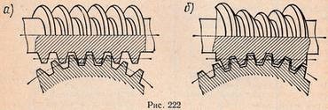
Figure 2–Types of worms
Worms are cylindrical (Figure 3.1, a) and globoid (Figure 3.1, b). The axial plane section of the turns of a cylindrical worm is a rack with straight or curved sides. The axial section of the globoid worm has the shape of a circular straight-sided rail.
Among cylindrical worms, the most widespread for irresponsible transmissions is the screw, or Archimedes, worm, which is, as it were, an ordinary screw with a trapezoidal thread. The helical surface of this worm is formed by rotation around the axis and the simultaneous movement along the axis (for each revolution) of a straight line passing through the axis of the worm and inclined at an angle to the axis; when sectioned by a plane passing through the axis of the worm, the turns have a trapezoidal profile (Figure 3.2, a). A worm pair with such a worm has a low efficiency and wears out quickly, so it is used in non-critical, low-speed and lightly loaded gears.
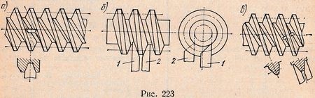
Figure 3–A variety of cylindrical worm
Another type of cylindrical worm is the involute worm (Figure 3.2, b). It is, as it were, a cylindrical gear wheel with a helical helical surface. In the section of the worm with planes perpendicular to the axis of the main cylinder, involutes are obtained, from which this worm got its name. Worm gear pairs with involute worms are often used in critical gears at high loads and speeds, but the manufacture of such gears requires the use of special equipment and complex processing methods.
Finally, the third type of cylindrical worm is a worm with a rectilinear profile in the normal section of the loop and with an elongated involute of the lateral side of the loop in the section transverse to the axis (Figure 3.2, c). Such a worm is called a convolute worm. It is a kind of involute worm. These worms are easier to process than involute worms, and provide sufficient precision in the engagement of the worm gear, have high efficiency and wear resistance.
Globoid worms have a large contact surface of the worm turns with the teeth of the worm wheel, which leads to a decrease in pressure, and, consequently, wear of the surface of the teeth of the worm pair. The helical thread of this worm is formed during the helical movement of the profile not along the cylindrical surface, but along the surface of the globoid. Despite the complexity of their manufacture, they are widely used in the transmission of high power.
5. Slicing worms
The simplest type of processing worms is cutting them on a lathe with a straight cutter. To obtain the correct profile of the turns, the profile of the cutter must have the contour of the cavity between the teeth of the worm in a certain section of it and coincide when cutting with the plane of this section.
To get an Archimedes worm, the profile of the cutter with straight edges must be aligned with the plane passing through the axis of the worm (Fig. 3.2, a). However, with an increase in the angle of rise of the turn, cutting the worm with one cutter becomes difficult due to a change in the size of the angle, which leads to failure of the cutting tool due to chipping of the cutting edge. Therefore, Archimedean worms at a large angle of elevation of the turns are replaced by involute or convolute ones.
An involute worm is cut with two cutters 1 and 2 (Figure 3.2, b), the profiles of the cutting edges of which are aligned with two planes tangential to the surface of the main cylinder on both sides. As the diameter of the main cylinder increases, the installation of the cutters above and below the center causes certain difficulties due to changes in the cutting angles, therefore, when cutting involute worms, profile cutters are used that correspond to the contour of the normal section of the worm cavity with the profile plane set normal to its axis.
The convolute worm is cut with a cutter set with its profile in a plane parallel to the worm axis, above or below it at a certain height or obliquely to it, with the alignment of the axis of symmetry of the cutter profile with the worm axis. Convolute worms with a straight working profile are processed with two incisors (Fig. 3.2, c).
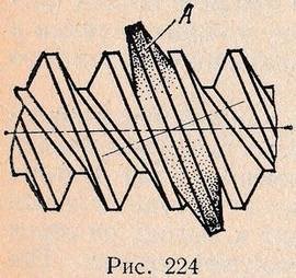
Figure 4–Cutting a worm with a disk cutter
Worms are also cut with a profile cutter and cutters on milling and thread milling machines. Cutting worms with a disc cutter is a more productive way of processing, but at the same time the profile of the worm is distorted as a result of undercutting, which occurs due to the difference in the angle of rise of the turn at the base and the top, especially in multi-thread worms. Therefore, this method is usually used for pre-processing the profile of the worm. When cutting with a disk cutter (Figure 3.3) with cutting edges of a straight profile, the axis of rotation of the cutter A is located at an angle to the axis of the worm, equal to the angle of rise of the turns of the worm.
Various types of worms can be cut with a hob cutter on conventional gear hobbing machines. So, when processing with a hob cutter with straight cutting edges of the tooth, involute worms are made. For cutting Archimedean and convolute worms, special hob cutters with a curved profile of the cutting edges are used. This high productivity machining method requires a sophisticated tool; since it leads to a distortion of the surface profile of the turns of the worm, it is used for preliminary processing.
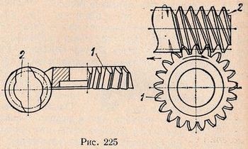
Figure 5–Cutting with a chisel
A productive method of processing, ensuring high accuracy, is cutting the worm on special machines (such as "Cornelis") with a chisel (Fig.3.4). The chisel 1 is imparted with the feed movement along the axis of the worm 2. In addition, the rotary motion of the running-in is imparted to the chisel and the worm. As a result of the combination of these movements, all the turns of the worm are cut. With this processing method, the surface profile of the worm is not distorted. However, the need to make chisels for each angle of elevation of the turns of the cut worms increases the cost of preparing for production, so the use of this method is economical only in large-scale or mass production.
Worm wheels are cut on hobbing machines with hob cutters in three ways:
- radial feed;
- tangential feed;
- combined method.
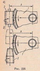
Figure 6–Tangential feed method
In the radial feed method (Fig. 6, a), the workpiece 1, being all the time in engagement with the hob 2, is fed in the direction of the cutter to the set size A, while the cutter makes only a rotational movement. The correct tooth profile is obtained on the worm wheel when the hob is fully engaged with the workpiece. The disadvantage of this method is that the worm cutter does not work with all cutting edges and only the blades of the middle part of the cutter wear out, which are constantly in contact with the workpiece. This method is used to cut the teeth of the worm wheel on a conventional hobbing machine without an additional special support. The setting of the chain of division of the machine is similar to setting when cutting spur gears with a straight tooth. Additional adjustment of the radial movement of the table is performed depending on the specified radial feed.
With the method of tangential feed (Fig. 6, b), the workpiece of the worm wheel 1 is set to the size of the center-to-center distance A and the cutter 3 is brought into engagement with the workpiece, moving it in the axial direction. Milling cutter 3 has a conical intake part and, working with all its cutting edges, wears out evenly. In the process of cutting, the cutter not only rotates, but also moves translationally along the axis. In this case, the workpiece 1, in addition to the main rotational movement associated with the engagement, must have an additional rotational movement, the speed of which depends on the axial movement of the cutter 3, otherwise the teeth of the cutter will cut the teeth of the workpiece. The axial movement of the cutter 3 and additional rotation of the workpiece 1 is carried out by a special support, which, when cutting worm wheels, is installed on a gear hobbing machine.
The combined method of cutting worm wheels is a sequential combination of methods of radial and tangential feeds, the first being used for preliminary cutting of teeth, and the second–for finishing. A corresponding allowance is left for final processing, which should compensate for the error of the previous processing. In the combined method, both worm cutters and profile cutters are used, and the use of the latter for the final processing of the worm wheel ensures high accuracy.
6. Selection of the necessary research methods
Due to the lack of direct functional dependencies between the errors in the processing of the cutter on the sharpening and backing machines and the resulting errors in the profile of the wheel tooth, the authors of the above work at that time did not manage to concretize the method for calculating the tolerances for the deviations of the elements of the cutter's tooth that form its producing surface.
As you know, the main parameters of any of the product quality characteristics are not only the absolute value of the scattering field of errors generated by the combined action of random factors, but also the middle of the scattering field, the coordinate of which, having its own sign and magnitude, determines the location of the scattering field n, c ultimately, the range of variation of the quality parameter. This must be taken into account when designing and manufacturing worm cutters for worm wheels to ensure smooth operation of worm gears.
Thus, in the field of assigning tolerances for the shaping of the profiles of the working and producing worms, the primary technological task is the distribution between the errors in the manufacture of the worm on the deviation of the profile of the transmission worm turn from the profile of the producing worm (the error of the helical surface of the worm turn as defined by G OST 3675-81 or tool producing surface error–according to the standard of the earlier edition).
The second task is based on the transfer smoothness norms. determine the positions of the midpoints of the tolerance fields for the geometric elements of the profiles of the worm and cutter, taking into account also the effect of periodic regrinding of the cutter.
The third task is to determine the influence of errors in setting the elements of setting up the grinding, backing and worm-grinding machines and assign tolerances to the vehicle elements that change during the processing of cutters and worms, in particular, the calculated radius (diameter) of the grinding wheel, profiled for processing the corresponding surface of the teeth of the hob or worm thread.
The overwhelming majority of worm gears used in machine-building and machine-tool building are designed on the basis of an Archimedean worm and, accordingly, the most widespread are worm cutters for worm wheels with a straight line or close to it initial contour in the axial section of the worm and the classical correspondence of the sizes of the producing and the worm cutter a working transfer worm.
However, in recent years, new directions have been identified in the field of research and improvement of technology for the production of worm gears, design and use of worm cutters for worm wheels:
- hob cutters and their machine setups for cutting worm wheels to gears with localized contact;
- the use of a unified tool for worm gear wheels based on the adjustment of the gearing pitch in the manufacture of worms (tool primary method);
- production of worm milling cutters for cutting globoid gear wheels;
- technological support for the production of hob cutters for gearwheels with fluid friction, gears with worms type 2T, etc.
Generalization and development of scientific and practical experience in the production of worm gears, including the design and manufacture of worm cutters for worm gears, taking into account the variety of currently used and promising types of gearing, described in subsequent chapters.
Conclusions
The paper considers: the requirements for worm gears, the reasons for failure and a decrease in the operational properties of worms; features of processing the profile of a worm wheel subjected to the application of wear-resistant coatings. The analysis of the considered processing methods and ways of their improvement is carried out. The goals and objectives of future research are set.
List of sources
- Александров Л. И., Артеменко Л. П., Костюк Д. И. Зубчатые передачи. Харьков: Издательство харьковского университета, 1964. 276 с.
- Бароне, Тордьон Точное распределение напряжений в стандартных зубьях и геометрические коэффициенты.//Труды американского общества инженеров–механиков, Серия В, 1973. № 4. С. 271-176.
- Аттиа Шум эвольвентных косозубых колес//Труды американского общества инженеров –механиков, Серия В, 1969. № 1. С. 179-186.
- Адам Я. И., Антонов О. И., Жарков В. В., Копф И. А., Овумян Г. Г. Чистовая обработка зубьев крупных закаленных колес // Вестник машиностроения, 1980. № 9
- Айрапетов Э. Л., Апархов В. И., Мельникова Т. Н., Филимонова Н. И. Неравномерность распределения статической нагрузки в косозубых и шевронных зубчатых передачах // Вестник машиностроения, 1997. № 10.
- Айрапетов Э. Л., Афонский Б Д., Генкин Б. Д., Луценко В. И., Мдинарадзе Н. И. Об анализе кинематической погрешности зубчатых передач с использованием фильтрации// Вестник машиностроения, 1985. № 3.
- Байков А. Н., Шрайбман С. М. Нарезание колес с малым числом зубьев на зубодолбежном станке // Вестник машиностроения, 1973. № 7.