
Abstract
Сontents
- Introduction
- 1. Theme urgency
- 2. Goal and tasks of the research
- 3. An approach to the unification of synthesis of Moore FSM on FPGA
- Conclusion
- References
Introduction
In recent years, it has been established that the surface quality of the last workpieces and their contamination with non-metallic inclusions. in the decisive degree of protection of the metal by the method of pouring from the steel-pouring ladle to the mold
The perfection of protection methods is also aimed at reducing the need for special expensive protective equipment, reduction of irrecoverable losses, elimination of malfunctions of low-skilled, hard work on the repair of workpieces and reduction of energy consumption for their heating after casting by rolling by the hot inlet method.
Protection in the continuous casting process is essential. The fact is that the casting process can last for hours, and during redistribution, continuously cast billets, as a rule, undergo less heating and less deformation. At the same time, due to the specific conditions of continuous casting, obtaining defect-free billets with minimal contamination with non-metallic inclusions is more difficult than when casting ingots into molds. Particular attention is paid to protecting the steel stream escaping from a casting or tundish during casting from contact with the surrounding air environment, which leads to secondary oxidation of the metal. In this regard, the development of new and improvement of existing methods of preventing contact of a jet of liquid metal with ambient oxygen is constantly underway [1-3].
1. Theme urgency
Currently, in metallurgy, more than 85% of all smelted steel is cast on continuous casting machines (CCM). The steel-pouring ladle, into which the metal is released from the steel-making unit after the end of the melting, is used for pouring steel into the continuous casting machine. Particular attention is paid to protecting the stream of steel escaping from the casting or tundish during casting from contact with the surrounding air, which leads to secondary oxidation of the metal. In this regard, the development of new and improvement of existing methods of preventing the contact of a jet of liquid metal with ambient oxygen is constantly being carried out. With out-of-furnace treatment, metal can be boiled and foamed during processing, therefore there is a free volume above the metal level in the ladle. A refractory pipe is used for casting steel from a ladle in the continuous casting machine.
Installation, holding and replacement of refractory pipes is performed using a special manipulator. During the long-term operation of this protective system, it turned out that the protective effect on the stream of metal flowing from the casting ladle, may turn out to be ineffective due to the existing design flaw in the used manipulator. Quite often, during the operation of a steel-pouring ladle, its metal bottom is subjected to warping under prolonged exposure to high mechanical and thermal loads, as a result of which the perpendicularity with respect to the vertical of the base surface of the flange welded into the bottom for fastening the shutter is violated, as a result of which the longitudinal axis of the tundish, and hence the steel jet, flowing out of the bucket at a speed of 10-14 m / s will also deviate from the vertical. In this regard, the consumption of expensive refractory pipes increases, and an increase in the intensity of secondary oxidation of steel is observed, due to air leaks through the formed gap between the bucket-collector of the bucket gate and the protective tube.
2. Goal and tasks of the research
The main purpose of this work is to research and improve the design of the manipulator for changing and holding protective pipes, which makes it possible to exclude uneven erosion of the protective pipe for screening the steel jet from the surrounding atmosphere at the section of the casting ladle - tundish of the continuous casting machine.
To achieve this goal, it is necessary to solve the following tasks:
1. Analyze the existing designs of manipulators for mechanized replacement of protective refractory pipes and identify their shortcomings.
2. Propose a new technical solution to eliminate the identified shortcomings. .
3. Analysis of existing designs of manipulators used to replace protective refractory pipes in continuous casting
Over the past decade, several design schemes of manipulation systems for changing and holding protective pipes have been patented, but one of them is most widely used in production, shown in fig. one. This structure is used, including at Donetskstal CJSC - a metallurgical plant.
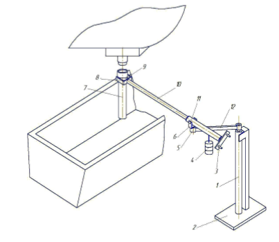
Figure 1 - Structural diagram of the manipulator for the replacement of protective pipes, used at most metallurgical enterprises during continuous casting of steel
It includes column 2, fixed on the base 1 and carrying the swing arm 12, at the end of which there is a bearing support 5 with a vertical fork 6, which holds the mouthpiece 11 on the trunnions. A rod 10 is installed in the mouthpiece on two bearing supports, equipped with a fork 8, which carries a support ring 9 on the trunnions to hold the protective refractory pipe 7, having the possibility of relative rotation in the vertical plane passing through the longitudinal axis of the rod 10. At the rear of the mouthpiece 11 there is a counterweight 4 and a handle 3 for manually turning the rod 10 in the horizontal and vertical planes while performing the required movements and orientation in space of the manipulated object - the protective tube. Many foreign metallurgical enterprises use the construction of the manipulator shown in Figure 2. This manipulator is equipped with a manual drive for the supply and installation of a protective pipe, it also has an acoustic emission control system for liquid metal outflow [4].
At many foreign metallurgical enterprises, the manipulator design shown in Figure 2 is used. This manipulator is equipped with a manual drive for the supply and installation of a protective tube, and an acoustic emission control system for the outflow of liquid metal is installed on it [5-7].
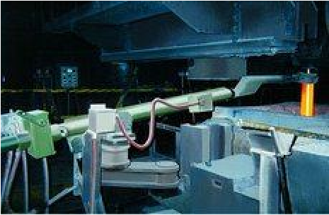
Figure 2 - The design of the manipulator used in many foreign enterprises
The boom is rotated to replace the spent protective tube and supply a new one to the bucket gate using a hand winch.
A similar design is used at the plant CJSC "Donetskstal" - a metallurgical plant "(Fig. 3). The bar is rotated using the side handles, the protective tube is fixed in the working position using a counterweight.
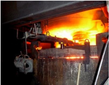
Figure 3 - The design of the manipulator used at the Donetskstal plant
Also, there is a design of this device offered by the NUMTEC-INTERSTAHL group of companies (Fig. 4), which is fully automated, equipped with a hydraulic drive and an electronic monitoring and control system.
With the help of a hydraulic drive, the required number of degrees of freedom is realized, which makes it possible to maximize the process of changing protective tubes, and exclude the possibility of a gap formation between the collector glass and the protective pipe [8].
The disadvantage of this design can be considered the presence of a complex and expensive drive, the exit from the operational state of a separate unit of which may result in long-term machine downtime.
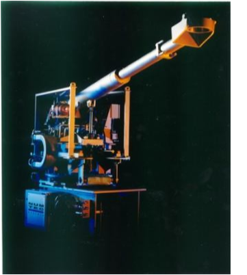
Figure 4 - Manipulator design proposed by the NUMTEC-INTERSTAHL group of companies
The practice of using such protective systems in steel shops of foreign and domestic metallurgical enterprises has shown that the efficiency of their use largely depends on the density of the joint between the nozzle of the casting ladle and the refractory pipe, and also from the ensured coincidence of the longitudinal axes of their channels. To improve the sealing of the joint, inserts made of plastoelastic material are used, consisting of a refractory filler, a low-melting inorganic binder, rubber and technological additives [9].
Based on the results of the analysis of existing structures, it can be concluded that none of them can fully protect the spilled metal from secondary oxidation and exclude the erosion of protective pipes. , due to the lack of the required number of degrees of freedom of the assembly holding the protective tube. This is due to the impossibility of ensuring the correct joining of the collector nozzle and the protective pipe, in case when the longitudinal axis of the tundish, and hence the steel stream emanating from the ladle, deviate from the vertical in an arbitrary direction.
Также, в большинстве рассмотренных выше конструкций, поворот удерживающей штанги относительно ее продольной оси осуществляется вручную , воздействуя на непосредственно связанный с ней рычаг или вращая лебедку, установленную на быстроходном валу редуктора, передающего крутящий момент штанге. В первом случае выполнение поворота штанги связано со значительными физическими нагрузками, а во втором с замедлением манипуляционной операции. В связи с чем, целесообразна разработка конструкции манипулятора , в которой вращение штанги относительно ее продольно оси будет производиться с помощью электромеханического привода.
Conclusion
The results of the experimental studies carried out allow us to conclude that that the industrial use of the improved manipulator will increase the indicators of the technical and economic efficiency of the use of refractory pipes in the conditions of the protection of steel from secondary oxidation during its technological overflow from the casting ladle into the tundish of the continuous casting machine. The positive effect will be obtained by reducing the number of cases of premature exit from building a protective refractory product due to intense local wear of its wall caused by the dynamic action of a jet of liquid steel on it. In addition, the likelihood of tightening the steel outlet of the casting ladle and the required flushing with oxygen should be expected.
Master's work is devoted to actual scientific problem of combining the basic methods of minimizing the instrumental Moore automata. In the trials carried out:
References
- Jungreithmeier A., Pessenberger E., Burgstaller K/ Production of UL CIF Steel Gradies at Voest-Alpine Stahl GmbH // Iron and Steel Technology. – 2004. – Vol. 1. №4. – P. 41-48.
- Еронько С.П., Быковских С.В. Разливка стали: Оборудование. Технология. – К.: Техніка, 2003. – 216 с.
- Металлургические мини-заводы / А.Н. Смирнов, В.М. Сафонов, Л.В. Дорохова и др. – Донецк: НОРД-ПРЕСС, 2005. – 469 с.
- Еронько С.П., Сотников А.Л., Ткачев М.Ю. Совершенствование системы быстрой смены погружных стаканов для серийной разливки стали на слябовых МНЛЗ // Металлургические процессы и оборудование. – 2012. – №3. – С. 26-38.
- New generation ladle slide gate system for performance improvement / J. Chaudhuri, G. Choudhury, S. Kumar, V. Rajgopalan // MPT International. – 2007. – Vol.30, №6. – pp. 38- 42.
- Mutsaarts P. Submerged entry nozzle exchange system for tundishes / Millennium Steel. – 2006. –pp. 143-146.
- Achieving higher perfomance & longer service life of Slide Plate / J. Chaudhuri, G. Choudhury, S. Kumar et. al. // Iron & Steel Review. – 2007. – June. – pp. 86-91.
- Еронько С.П., Сотников А.Л., Ткачев М.Ю. Совершенствование системы быстрой смены погружных стаканов для серийной разливки стали на слябовых МНЛЗ // Металлургические процессы и оборудование. – 2012. – №3. – С. 26-38.
- Кащеев И. Д., Ладыгичев М. Г., Гусовский В. Л. Огнеупоры: материалы, изделия, свойства и применение. // Москва: Теплоэнергетик, 2003. — 336 с.
- Еронько С.П., Ткачев М.Ю., Понамарёва Е.А. Модельные исследования влияния вибрационного воздействия на процесс зарастания канала ковшового затвора // Черная металлургия. Бюллетень научно-технической и экономической информации, 2018. № 11. – С. 51 – 58.
- Еронько С.П., Ошовская Е.В., Ткачев М.Ю., Понамарёва Е.А. Модельные исследования параметров работы вибрационных устройств для систем ковшовых затворов. // Сборник научных трудов ГОУ ВПО ЛНР «ДонГТУ», № 11 (54). – Алчевск, 2018. – С. 119 - 128.