
Abstract
- Introduction
- 1. State of the issue. Purpose and objectives of the research
- 2. Main conveyor transport as an automation object
- 3. Critical review of existing technical solutions in automated control of main conveyor transport
- 4. Development of a simulation model of the underground transport system of a mine
- 5. Development of an algorithm for controlling mine underground conveyor transport
- 6. Practical implementation of an automatic control system for the main conveyor transport of mine
- Conclusions
- List of references
Introduction
Conveyor transport has assumed a dominant position in coal mines since the mid-70s of the last century. The modern underground transport complex of a coal mine is represented by an extensive system that performs technological transport tasks.
1. State of the issue. Purpose and objectives of the research
Due to the peculiarities of the technological process of mining and transportation of minerals, underground conveyor transport constantly operates in conditions of uneven cargo flows.
The productivity of conveyor lines in most cases is significantly overestimated, which is associated with the changing topology of the transport network of the mine [1]. This reduces the load on the conveyor lines, which reduces the utilization rate of the conveyors included in the line [2].
Such a performance margin is laid in the absence of the possibility of managing the unevenness of the existing freight flows distributed in space and time.
Taking into account one of the modern trends in the development of mining enterprises, which is to reduce the cost of electricity for the extraction of minerals, it is possible to formulate the goal of the work – increase the efficiency of the main conveyor transport in conditions of uneven cargo flows by creating an automatic control system.
To achieve this goal, it is necessary to solve the following tasks:
- explore the technological process of the main conveyor transport of mine;
- analyze existing technical solutions in the field of automation of underground conveyor transport;
- develop a simulation model of the underground transport system of mine that works in conditions of uneven cargo flows;
- investigate modes underground conveyor transport together with storage bunkers to determine a combination of parameters which provides the minimum specific energy consumption;
- develop technical solutions for the practical implementation of an automatic control system for the main conveyor transport of mine.
2. Main conveyor transport as an automation object
Underground conveyor transport is a sequential technological chain, consisting of district and the main transport, and accumulating bunkers, which is united by a cargo flow formed by coal faces. In places where various elements of the transport network merge, solid material is reloaded from one conveyor to another, or freight flows from several faces are summed up onto a collecting conveyor.
For underground conveyor transport, there are three basic modes of operation: start, work, stop.
Starting mode is the most severe mode, which can be accompanied by significant dynamic loads and moment of resistance. Therefore, the automation equipment must implement a soft-start in order to provide shock-free starting in the transmission at the initial moment and prevent slipping of the belt on the drive drum. In addition, there is a need for a minimum starting time in order to reduce the time the drive motors are exposed to inrush currents. The start of the conveyor transport is carried out in the direction opposite to the cargo flow, while each next conveyor is started only after the nominal speed of the previous conveyor has been established.
In work mode, the mineral is transported from the coal face by district conveyors to the main conveyor lines and then to the mine lift. In this case, various emergency situations can arise.
The stopping of the conveyor transport is carried out by a command from the operator and in the event of an emergency or threat. An automatic stop of conveyors transporting cargo to a failed conveyor and blocking of repeated remote switching on when any protections are triggered should be provided.
3. Critical review of existing technical solutions in automated control of main conveyor transport
At present, the following automation tools and systems are used in the automation of underground conveyor transport: UKL.1, AUK.1M and AUK.2M.
The automation tools and systems presented above are widely used. However, they have the following limitations: moral and technical obsolescence; inability to control long conveyor lines, which consist of many conveyors, and also have many branches; the impossibility of energy efficient operation in conditions of uneven cargo flows coming from the branches to the collecting conveyor, which leads to idle operation, etc.
Modern microprocessor-based computer-integrated automated systems for monitoring and control of underground conveyor transport in mines include: AUK.3, SAUKL, ASKU KL, ASU KL, UTAS transport chain control subsystem.
These complexes are representatives of modern automation equipment for underground conveyor transport of mines; however, they also have limitations: inability to provide fully automatic control of thermal conditions of individual conveyor elements (drive drum, conveyor belt, roller supports), which can lead to emergencies; impossibility of time synchronization of bunker equipment operation in conditions of uneven cargo flows.
Based on the analysis of the capabilities and composition of these complexes, the AUK.3 complex was adopted as the basic equipment for automated control of the main conveyor transport of the mine.
The AUK.3 complex is a further development of the capabilities of the AUK.1M equipment and provides more than 70 functions for control, blocking and signaling. Main functions:
- control of the conveyor line (telemechanical channel);
- control of conveyor mechanisms (starters of drive motors and brakes);
- control of protection and blocking of the conveyor (including slip of the drive drum);
- display and transmission of information (in text form) to the control panel;
- determination of the type of triggered sensor in the conveyor line, etc.
4. Development of a simulation model of the underground transport system of mine
To analyze the structural diagram of the underground transport network of the mine, a simulation model has
been developed that takes into account the random nature of cargo flows, technological parameters and
operating modes of the elements coal face
, conveyor line
, accumulating bunker
and
lifting machine
. Simulation modeling of the transport network was carried out using Petri nets
[8].
Arcs connecting many positions with many transitions have two directions – from position to transition and back. The weight of an arc determines the number of tokens that it transfers per unit of time from one element of the system to another. The weight of the arcs of the conveyor line model is determined by the conveyor with the lowest throughput (theoretical performance). The weight of the arcs of the lifting machine model is determined by the lifting capacity of the hoisting vessel used.
Figure 1 shows the developed simulation model of the underground transport system of mine in the form of a Petri net. The study of the simulation model of the transport network was carried out using the HPSim 1.1 software package.
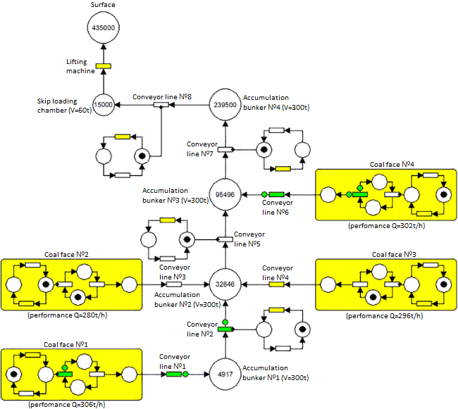
Figure 1 – Simulation model of the underground transport system of mine
A continuous flow is determined by the movement of discrete volumes of cargo with a conventional weight of one kilogram along the transport network. The simulation time was 21,600 units, which corresponds to a six-hour work shift at the mine. The results of simulation modeling of coal faces, accumulating bunkers and the process of transporting minerals to the surface of mine are presented in Figures 2, 3 and 4.
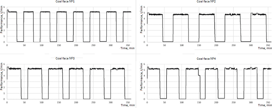
Figure 2 – Results of modeling of coal faces
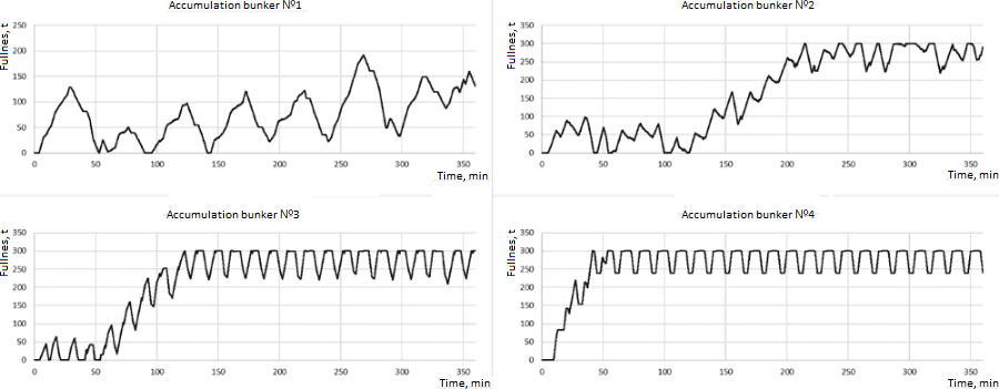
Figure 3 – Results of modeling accumulation bunkers
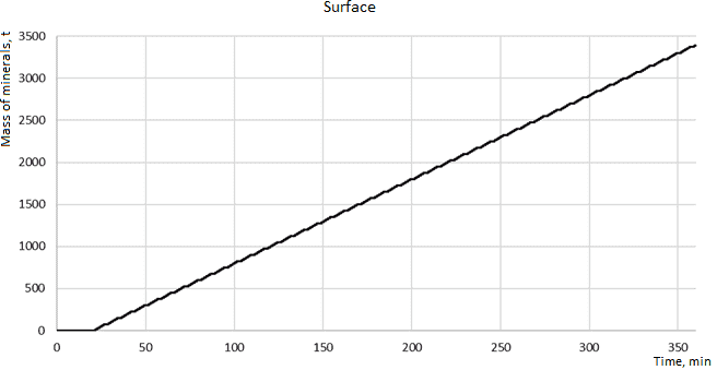
Figure 4 – Results of modeling the coal flow to the surface of mine
Analysis of the simulation results shows that regulation of the productivity of the main conveyor transport reduces the time of unproductive use of transport equipment, increases the energy efficiency of the conveyor transport, and increases the service life of technological equipment and installations.
5. Development of an algorithm for controlling mine underground conveyor transport
During the stoppage of the transport system of the mine, the coal faces must have the same operating time for the common accumulation bunker. Based on the above, the rational level of filling the bunker with solid material is determined from the expression:
where Hmaxb – maximum bunker loading height, m;
Xj – average cargo traffic from the coal face j, m3/min;
Sib – cross-sectional area of the bunker i, m2;
Hib – level in the bunker i, m;
Sjb – cross-sectional area of the bunker j, m2;
Xi – total cargo flow from coal faces to bunker i, m3/min;
k – number of bunkers.
The moment of switching on the bunker feeders is determined by their conditional number according to the criterion of transport delay. If, after the bunker feeder with a lower conditional number, a feeder with a larger conditional number should be switched on – in order to prevent spilling of minerals, switching on should occur after the moment the belt is freed from the load under the feeder. If after the bunker feeder with a larger conditional number, a feeder with a lower conditional number should be switched on – to exclude the idle mode for the time of the transport delay, the time of switching on the feeder i is determined from the expression:
where ti−1on – time of turning on the feeder of the previous bunker;
tclbf – bunker cycle time, min;
Ttd – transport delay from a bunker with a larger conditional number to a bunker with a smaller conditional number, min.
The bunker feeders are switched on sequentially, according to the criterion of the maximum deviation of the predicted value of the solid material level from the calculated value at the time of unloading the bunker. The predicted value of the level of solid material in the bunker for the current time is determined from the expression:
where Hjb – level in the bunker j, m;
Xi – total cargo flow from coal faces to bunker j, m3/min;
Tjpac – transport delay of the last unloaded package, min;
Tjb – transport delay of the bunker j, min;
X3 – averaged over one cycle of work value of the minute cargo flow from the feeder, m3/min;
Sjb – cross-sectional area of the bunker j, m2.
In order to improve the efficiency of the underground conveyor transport, an automated control system has been developed, the functioning algorithm of which is shown in Figure 5.
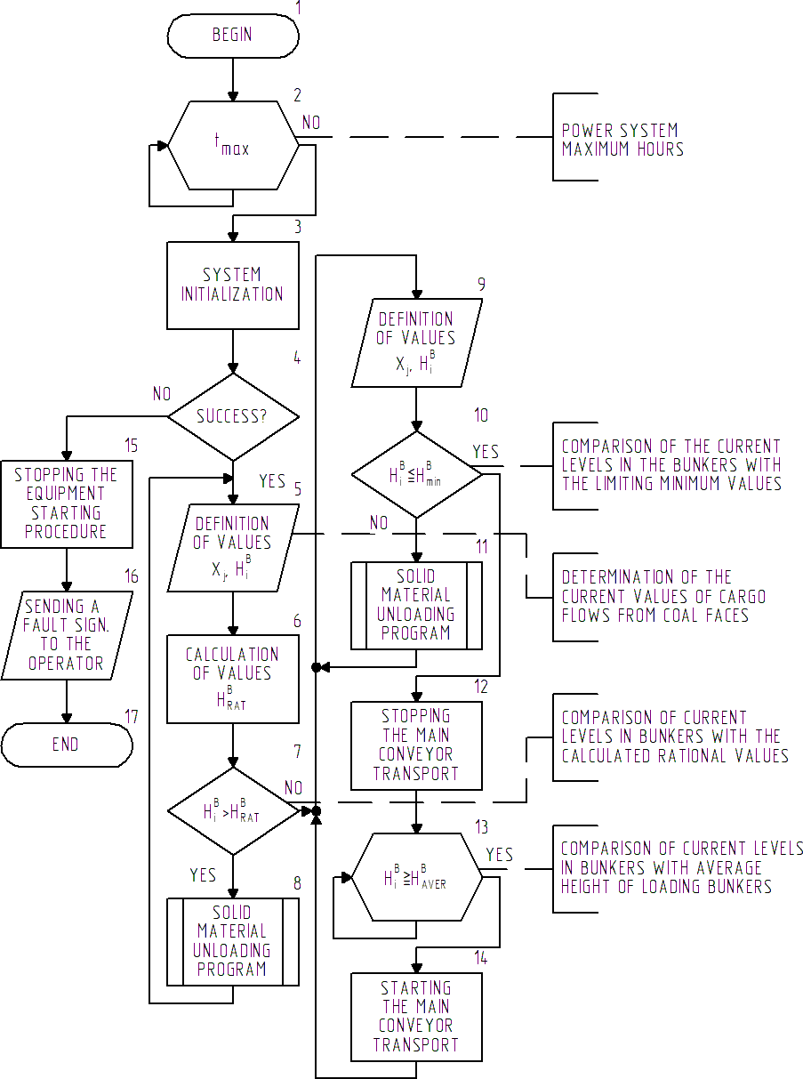
Figure 5 – Algorithm of the mine conveyor control system
The bunker unloading process includes preparing the transport system for operation and unloading the mineral from the bunkers to the minimum allowable loading height. Before starting work, the automated control system checks the condition for the prohibition of operation during the maximum hours of the power system tmax with the subsequent initialization of the elements.
Upon successful initialization, the current values of cargo flows from the district bunkers Xj and the levels of solid material in the bunkers Hib are evaluated.
The rational levels of loading bunkers with minerals Hratb are determined. If the actual values of the level of solid material in the bunkers exceed the calculated values, the program for unloading the solid material is initiated (Fig. 6).
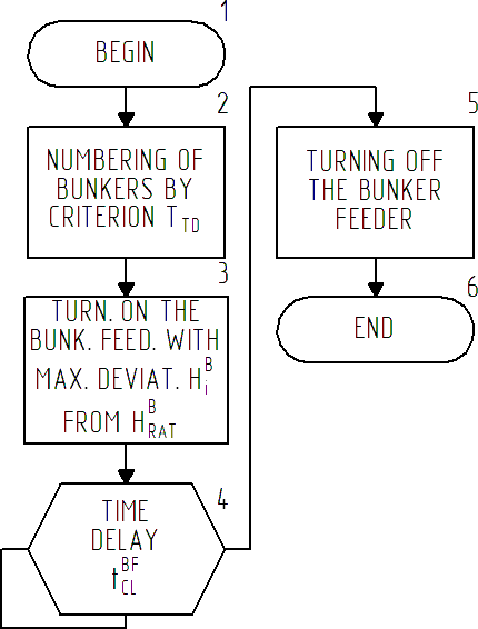
Figure 6 – Block diagram of the solid material unloading program
According to the updated data, the next bunker is selected with the greatest deviation of the current loading level Hib from the calculated rational value Hratb. The preparation of the transport system for work continues until the actual levels of loading the bunkers with solid material are less than or equal to the calculated values. If the system has not been initialized, the equipment startup procedure is stopped. At the same time, information about the nature of the malfunction is transmitted to the system operator.
Next, the mineral is unloaded from the bunkers to the minimum loading values Hminb. At this time, the current values of cargo flows from the coal faces Xj and the levels of solid material in the bunkers Hib are monitored. If the actual values of the levels of solids in the bunkers exceed the minimum loading heights, the execution of the unloading program for solids is initiated (Fig. 6).
After reaching the minimum loading heights in the bunkers Hminb the main conveyor transport is forced to stop. The resumption of the work of the main conveyor transport occurs when the average loading height of a separate bunker, which is part of the transport chain, reaches the average height Haverb.
6. Practical implementation of an automatic control system for the main conveyor transport of mine
The structure of the monitoring and automatic control system for the underground conveyor transport of the mine is a computer-integrated two-level control system, the elements of which are interconnected by an industrial information network.
The upper level is a system of centralized automated monitoring and control of underground mine transport, which performs the following functions:
- diagnostics and graphical display of the state of each conveyor;
- deciphering the reasons for emergency and operational stops in graphic and in text form (comments);
- logging of technological process parameters and history of the control process;
- formation of advice on the operational management of conveyor transport, depending on the traffic.
At the lower level, the system is represented by two subsystems: a conveyor transport control subsystem and an accumulating bunkers control subsystem. The generalized block diagram is shown in Figure 7.
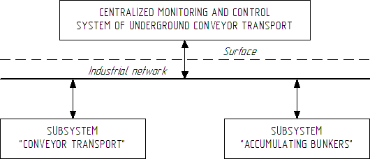
Figure 7 – Scheme of the automatic control system for the underground conveyor transport of mine
The upper layer data network is industrial Ethernet, operating according to the PROFINET standard, which uses the TCP/IP, RT and IRT protocols.
The lower level is an electrical network with an RS-485 bus topology, which operates according to the Profibus standard with the Profibus DP protocol.
To carry out automatic measurement of the mass of solid material on conveyors, automatic conveyor scales VKAU are used.
Automatic control of the thermal modes of operation of the conveyor elements is carried out by the AKTL-1 equipment.
Continuous measurement of the filling levels of the accumulating bunkers is carried out by the equipment for monitoring the level of the rock mass AGKM.
Conclusions
As a result of the analysis of the technological process of the main conveyor transport, the requirements for the automatic control system are formulated.
An analysis of existing technical solutions in the automation of underground conveyor transport showed that the systems and automation tools presented on the market have limitations, which include the impossibility of energy efficient operation in conditions of unevenness incoming freight flows, as well as the lack of control over the thermal modes of operation of the conveyor elements.
A simulation model of the underground transport system of the mine has been developed, which operates under conditions of uneven incoming cargo flows.
During the study of the operating modes of underground conveyor transport, together with accumulating bunkers, an algorithm for the automated control system of mine conveyor transport was developed. It allows to reduce the unevenness of the incoming freight traffic, increase the energy efficiency of mine conveyor transport, and increase the service life of the technological equipment.
The automatic control system of mine's main conveyor transport is implemented on two levels using
industrial networks. The upper-level subsystem adopted the industrial Ethernet standard using the
protocols: TCP/IP, RT and IRT. The subsystems of the lower level Conveyor transport
and
Accumulating bunkers
are organized using an industrial network of the Profibus standard using
the Profibus DP protocol. To expand the functionality of mine's main conveyor automatic control
system, additional automation systems and information selection tools are included: VKAU,
AKTL-1 and AGKM.
At the time of writing this essay, the master's work has not yet been completed. Final completion: June 2021.
List of references
- Шахмейстер, Л. Г. Вероятностные методы расчета транспортирующих машин [Текст] / Л. Г. Шахмейстер, В. Г. Дмитриев. – М.: Машиностроение, 1983. – С. 67–69.
- 2Петков, О. Н. Разработка и исследование системы автоматического управления скоростью
ленточного конвейера по входному грузопотоку: автореф. дис. на сосиск. уч. степени
канд. техн. наук: спец. 05.13.07
Автоматизация процессов управления
/ Петков О. Н. – Москва, 2007. – 20 с. - Заика, В. Т. Методы повышения эффективности электроснабжения и энергоиспользования подземных горных машин и установок угольных шахт: Дис. д-ра техн. наук: 05.09.03 / [Национальная горная академия Украины]. – Днепропетровск, 2001. – 350 c.
- Шахмейстер, Л. Г. Тяговые расчеты ленточных конвейеров / Шахмейстер Л. Г., Дмитриев В. Г. – М. [МГИ]. 1969. – 108 с.
- Разумный, Ю. Т. Энергосбережение / Разумный Ю. Т., Заика В. Т., Степаненко Ю. В. – Днепропетровск: [НГУ], 2008. – 164 с.
- Рудничный транспорт и механизация вспомогательных работ / Под ред. Б. Ф. Братченко. – М.: Недра, 1978. – 423 c.
- Шахмейстер, Л. Г. Подземные конвейерные установки / Л. Г. Шахмейстер, Г. И. Солод. – Москва: Недра, 1976. – 429 с.
- Васильев В. В., Кузьмук В. В. Сети Петри, параллельные алгоритмы и модели мультипроцессорных систем. – Киев.: Наук. Думка, 1990. – 212 с.