
Abstract
This abstract is used as an example, with the permission of Evgeniy Tatolov.
Original: http://masters.donntu.ru/2011/fknt/tatolov/diss/indexe.htm
Content
- INTRODUCTION
- 1.MATERIALS AND TECHNOLOGIES FOR MANUFACTURING SLOTTED SIEVES FOR SCREENING AND DEWATERING OF MINERAL AND ORGANIC RAW MATERIALS
- 2.WELDING OF STAINLESS STEELS
- 2.1.Effect of gas purity on welding
- 2.2.Welding mode
- 3.PROCESSING OF RESULTS
- References
- 2.2.Welding mode
Introduction
Slotted sieves are mainly used as surfaces for technological applications in thickening and dewatering processes, pressing, drying, fermentation in the food processing industry, sugar making, malt making and many other industries (brewing, confectionery, meat processing industry, etc.). they are also used in chemical and pharmaceutical industries and processing industry for similar technology, in coal and mining processing processes, in dewatering various slurries and slurries at wastewater treatment plants, etc[1].
The slotted surfaces of sieves can withstand a significant load per unit area (up to several hundred kg). The working surface is smoothly processed, it has a smooth, cylindrical or other shape (cones, round, parabolic surfaces, etc.). for increased loads and to increase the strength of the screen surface in technological equipment, it is necessary to apply strengthening technologies.
1.MATERIALS AND TECHNOLOGIES FOR MANUFACTURING SLOTTED SIEVES FOR SCREENING AND DEWATERING OF MINERAL AND ORGANIC RAW MATERIALS
Shpaltovy sieves represent flat cards with a smooth surface and are collected from separate wire grates of a shaped profile with cuts, eyes or turns for the bearing or connecting rails or hairpins located at a certain distance from each other perpendicular to the direction of the grates [2]. For the manufacture of wire grate nets should be used:
- Steel wire grades 08H18N10, 12H18N9, 12H18N9T, 12H18N10T, 10H17N13M3T heat-treated light annealing or etched according to NTD;
- 12Х13 steel wire heat treated oxidized according to GOST 18143;
- Low-carbon steel wire 08KP; 10; 15; 20 according to NTD.
For meshes with a gap size of up to 0.3 mm inclusive, heat - treated, light annealed, high-precision steel wire should be used-low-carbon according to specifications 14-4-1563, high-alloy according to specifications 14-4-1571, and brass semi-hard or soft high-precision wire according to GOST 1066 [3].
2.WELDING OF STAINLESS STEELS
Chromium steels are prone to air-quenching, which is highly dependent on the carbon content. Steels with a very low carbon content (≤ 0.08% C), such as 0x13 steel, are best welded. Steel grade 1X13 is more hardened, because when heated about 1000 & deg;S, it becomes completely austenitic and when cooled even in air, a γ - M-transformation occurs.
When welding ferritic steels with 14-28% Cr, the welds are brittle and often crack. Therefore, steel welding should be performed in a preheated state at & azimp; 200 & deg;C, the heating time of the metal during welding should be minimal. Better results are obtained with electric arc welding than with gas welding. After welding, it is recommended to heat the welded joint to 720-780 & deg;C and cool it quickly.
Steels with 15-17% Cr are sometimes undercut during welding. To avoid this, it is recommended to use steel with an additive of titanium or niobium, and in the case of steel with 13% Cr-with an additive of 1% Al [4].
Austenitic steels have a lower melting point (1400°C), lower thermal conductivity, and a higher coefficient of linear expansion than carbon steels. Therefore, when welding these steels, the melting is faster with a large temperature difference from the weld to the base metal. Titanium-or niobium-stabilized steels such as 00X18H10, 0X18H10, and X18H9 are prone to intergranular corrosion during welding, and the higher the carbon content [4].
2.1 Effect of gas purity on welding
Usually, tungsten electrode welding in an inert gas (TIG) environment is advisable for welding metals up to 7.0 mm thick. If the thickness does not exceed 1.5 mm, the use of other methods of arc welding is impractical due to the risk of burns. When argon-arc welding in an argon or helium environment, there is minimal carbon monoxide of alloying elements and the stability of the arc increases.
Welding of austenitic stainless steels can be performed with a continuously burning or pulsed arc. Due to the features of the thermal effect, the pulse arc allows you to reduce the width of the near-seam zone and warping of the parts to be welded, as well as to weld metal of small thickness and ensure good seam formation.The lower the content of H2O in the protective medium, the higher the thermal conductivity of the arc, which ensures a higher temperature of the welding bath. Thus, the use of high-purity argon contributes to a more complete gas release from the melt in the welding zone, therefore, the probability of pore formation is reduced[5].
The argon supply mode and the amount of argon in the burner must be optimal and stable. It should be particularly noted that increasing the gas supply speed often does not improve, and sometimes worsens the quality of the protective environment. At high pressure and high gas velocity, a turbulent flow occurs in the burner, which causes argon to mix with air in the welding zone [5].
2.2 Welding mode
The mode of automatic and mechanized welding with a melting electrode in protective gases is characterized by the wire diameter, arc voltage, wire feed rate and associated current, and protective gas consumption.Approximate modes of automatic and mechanized welding with a melting electrode are shown in figure 2.1.
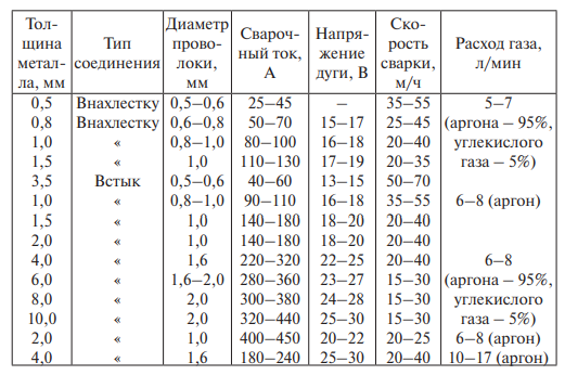
Figure 2.1-Modes of automatic welding of butt joints made of austenitic chromium-Nickel steels with a melting electrode (SV-04H19N11M3 wire) [5]
Regardless of the size of the product to be welded, the optimal wire feed rate with a diameter of 0.8-1.2 mm can be considered 400 m / h. The welding current will be about 120-140 A [6].
The choice of wire grade is determined by the grade of steel to be welded, the welding method, and the conditions under which the welded structure operates. Wire with a diameter of up to 1.6 mm, designed for automatic argon arc welding, is stretched to give it greater rigidity for better passage between the rollers and in the mouthpiece. It is very important to get the cold deformation constant along the length, and a certain degree [6].
3.PROCESSING OF RESULTS
A weld during fusion welding is formed at the junction of metal workpieces as a result of fusing the filler material with the one being welded. In the resulting welded joints can be divided into three zones, differing from each other in a structure: area of deposited metal (seam) – I, heat-affected zone (heat affected) – II, zone of the base metal to III. The structure and properties of the metal of the last zone do not change during the welding process. The metal of the seam and the near-seam zone undergoes phase transformations due to heating and subsequent cooling. Therefore, the quality of the welded joint is mainly determined by the properties of the metal of these two zones.
The study of the microstructure begins with the examination of the microchip under a microscope before etching. This allows you to identify microdefects: pores, cracks, non-metallic inclusions.
Welding was performed on grates made OF 20X13 steel to which stiffeners made of various wires were welded. The treatment was carried out using TIG and MIG methods in an installation that included gas cylinder equipment, a tungsten electrode and a device for moving it.
One or more hardened tracks were applied to one of the faces of the samples. The macrostructure was studied with the naked eye and using an MBS-9 microscope.
Figure 3.1 shows a slotted sieve from which 18 samples were cut.
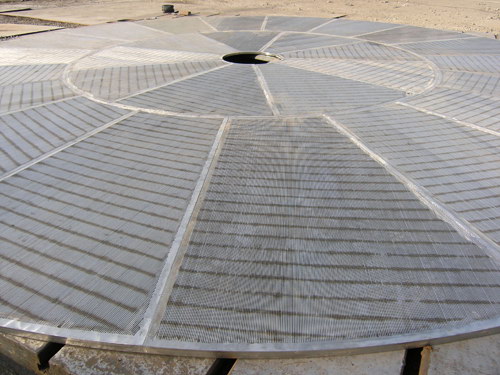
Figure 3.1 – The sieve slit is welded to the filter-Chan
Cross sections were made on the samples according to the usual method. Surface preparation, grinding and polishing of samples are carried out using abrasive materials and tools. Abrasive materials are sandpaper from coarse to fine abrasive.Micro-sand preparation consists of several sequential processes: preparation of a flat surface, grinding and polishing.A flat surface is prepared on the end surface of the sample. The samples were processed on a rotating grinding wheel.
In the manual method of sanding, a sanding skin is placed on a hard flat lining (thick glass) located horizontally. The sample is placed on the paper with a blocked plane and sanded sequentially in mutually perpendicular directions with light pressure until the drawings left after facing are completely destroyed. After finishing grinding on the skin with the smallest grain, the sample is washed with running water and polished.To finally level the surface, the section is polished to a mirror Shine. The section is mechanically polished on a polishing machine. When polishing, the slot is periodically rotated to more evenly process the entire surface.
The microstructure was studied on the sections using a neophot–21 microscope. The structure was identified by the Kovalenko etcher No. 14.Figures 3.2 and 3.3 show the microstructure of rib sample No. 2.
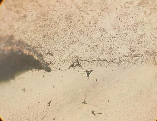
Figure 3.2 – Sample No. 2 (SV-08 filler wire) X600
Figure 3.2 shows the crack that appeared after welding.
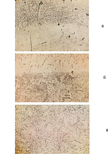
Figure 3.2 – The microstructure of sample No. 2 (welding wire SV-08) X600
Сonclusions
Increasing the carbon content in steels, on the one hand, improves the properties of the welded joint due to heat treatment, and on the other hand, it worsens the weldability due to embrittlement of the HAZ. The correct choice of the thermal mode of welding allows you to eliminate these difficulties. Unacceptable defects of welded joints and seams detected by external inspection are.
- Cracks of all sizes and directions;
- Local swells with a total length of more than 10 mm on the 1000 mm seam section;
- Undercuts with a depth of more than 0.5 mm with the thickness of the thinnest of the welded elements up to 20 mm inclusive;
- Incomplete craters.
It was found that when using the SV-08 filler wire, a crack appeared on sample No. 2. From the photos of the microstructure of sample No. 2, the structure of the grate and the weld consists of martensite.
References
- Щелевые сита: Каталог продукта [Электронный ресурс]. – Режим доступа: http://www.ruseurositex.ru/docs/slotted_sieve.pdf
- Вайсберг, Л.А., Просеивающие поверхности грохотов. Конструкции, материалы, опыт применения /Л.А. Вайсберг, А.Н. Картавый, А.Н. Коровников // СПБ.: Изд-во ВСЕГЕИ. - 2005. — 252 с.
- ГОСТ 9074-85 Сетки щелевые на соединительных шпильках. Технические условия (с Изменениями N 1, 2). - Введ 1987-01-01.- М.: ИПК Издательство стандартов, 2003
- Химушин, Ф.Ф. Нержавеющие стали .- М: Металлургия, 1966. – 776 с.
- Белугин, К.Н. Преимущества использования продукта ARCAL 1 TM (99,998% Ar) для сварки аустенитных нержавеющих сталей / К.Н. Белугин, В.В. Бисин, И.М. Лозинский // Металлообработка. – 2012. - № 4. – С. 47-50.
- Масаков, В.В. Сварка нержавеющих сталей: учеб. пособие / В.В. Масаков, Н.И. Масакова, А.В. Мельзитдинова. – Тольятти: ТГУ, 2011. – 184 с.