
Abstract on the topic of graduation work
Content
- Introduction
- 1. Design features of continuous casting molds
- 2. Sleeve molds CCM
- 3. Prefabricated molds CCM
- List of sources
Introduction
The mold of the continuous casting machine is a water-cooled mold, the inner surface of which is exposed to the abrasive effect of a moving crystallizing steel ingot. The mold is the most important component of the continuous casting machine. It provides fast formation of a sufficiently thick, strong "crust" on the surface of a continuously cast billet.
1. Design features of continuous casting molds
Structurally, the mold (Picture 1.1) is a complex assembly unit, which includes an internal copper jacket, which is in direct contact with the molten metal, and a rigid steel body, which serves to fix and support the copper jacket. A gap is provided between the copper walls of the mold and the steel body, through which cooling water is passed at a certain rate.
Until recently, the usual technological length of the mold was 700-800 mm with the minimum dimensions from 500 mm to the maximum 1200 mm. The modern concept of molds assumes a length of the order of 900-1000 mm, which increases the thickness of the hard shell of the billet at the exit from the mold when casting at higher speeds.
The working part of the crystallizers is made either from refined copper, or from an alloy of copper with silver or copper alloys with chromium and zirconium. To increase the operational resistance, special protective coatings based on chromium or nickel are applied to the inner surface of the mold.
Chrome plating is a traditional wear-resistant coating of the inner surface of the mold. It is used directly on copper plates when casting blooms and billets, as well as as a wear-resistant coating that weakens friction between nickel and copper in slab caster. The hardness of chromium is about 900 HV, but the thickness of the chromium spraying is limited to 0.12-0.13 mm (in slab caster) and approximately 0.20-0.22 mm (bar caster). To date, the main tasks of its application are to reduce friction and reduce adhesion in the mold with a sharp change in the metal level at startup.
In recent years, nickel and nickel alloys have been successfully used as a protective coating, which has certain advantages in terms of regulating the intensity of heat removal. The hardness of such coatings varies from 220 to 1200 HV, and the thermal conductivity - from 90 to 30 W / (mK). In practice, nickel coatings are used for slab continuous casting machines, which have different thicknesses along the height of the mold. This makes it possible to expand the possibilities of controlling the heat removal process in the mold, which is especially important for crack-sensitive steel grades.
In addition, the leading manufacturers of crystallizers use various types of three-layer coatings such as nickel (+ phosphorus) - cobalt - chromium, which significantly increase the durability of the sleeves, but at the same time slightly increase their cost. Structurally, the copper part of the crystallizers is made either in the form of a sleeve or a prefabricated.[1].
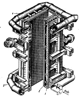
Picture 1.1 – General diagram of the mold of continuous casting machine
2. Sleeve molds CCM
Sleeve molds (Figure 2.1) are usually used for casting a square billet with a cross-section up to 220-250 mm, as well as for casting a round billet.
Shell molds are made of solid-drawn copper pipes with a wall thickness of 5 ... 20 mm. A part with a given cross-sectional profile, called a sleeve, which is the inner working wall of the mold, is obtained from a pipe billet by various methods of metal forming. The sleeve is inserted into a steel body and fixed at the top with a flange. The lower part of the sleeve is fixed in the body using a seal that allows free thermal expansion without deforming the walls. Water moves between the body and the sleeve along a gap of 4 ... 7 mm, providing intensive and uniform heat removal. Liner warping is also prevented by reinforcing ribs. [1].
A great advantage of the shell molds is the ability to achieve high casting speeds due to the high intensity of heat removal through the thin walls of the shell, the absence of joints in the working surface of the wall, which often cause the ingot to hang, low copper consumption, easy replaceability of worn-out shells, as well as simplicity of design and relatively low cost. However, shell molds are unsuitable for casting rectangular and large square sections due to insufficient stiffness of thin-walled copper shells, and they are practically not restored during repairs. The operational durability of shell molds can be 20-25 thousand tons of liquid steel. The intensity of heat removal in the sleeves increases significantly due to a decrease in the size of the air gap between the wall of the mold sleeve and the crust of the continuous ingot. The air gap can be eliminated, or at least reduced to a minimum, and heat transfer is optimized, if the mold contour is as close as possible to the continuous ingot shell contour. In practice, a correction for natural shrinkage of a continuously cast ingot is carried out by making the inner surface of the mold sleeve either in the form of a multistage cone, or in the form of a so-called parabolic profile. This concept in general provided an increase in the drawing speed of the workpiece by an average of 1.5-2.5 times in comparison with single-cone and double-cone sleeves.
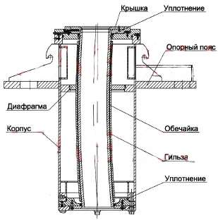
Picture 2.1 – Sleeve mold of section continuous casting machine, assembled
3. Prefabricated molds CCM
Prefabricated molds are a four-plate copper structure and are used for bloom and slab caster. Copper working walls are made thick enough (50-60 mm) and grooves are cut in them for the passage of cooling water. The mold length is usually 0.7-1.1 m.
There are 2 types of prefabricated mold designs: fan-shaped and box-shaped. The fan pattern is mainly used for bloom caster. In this case, after a certain wear of the inner surface, the plates are rearranged, which allows them to be used up to 5-6 campaigns. The box structure is used for slab and bloom caster. This design makes it possible to change the width of the slab and bloom during casting, as well as to change the taper of the side faces. In this case, the inner surface of the molds has a protective coating.[1].
The design of the slab molds has a box-shaped architecture. At the same time, the design of modern slab molds provides for the possibility of moving the side walls both in order to change the width of the cast slab and in order to correct the taper of the side edges during the casting process. Changing the slab width in the course of casting is achieved by sufficiently slow movement of the narrow-faceted plates in the required direction. The maximum rate of change in the slab width is estimated at 200 mm per minute due to a carefully selected sequence of movement of the narrow side of the mold. Adjusting the slab width directly during casting can increase the productivity of the continuous casting machine by 30-50%, reduce the cost of refractories by 30-50%, and significantly save energy. The reduction in the width of the mold is carried out at the head of the first melt slab with a smaller width.
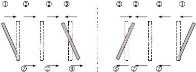
Picture 3.1 – Scheme of reducing the width of the mold during casting: 1 - reducing the wedge shape to zero; 2 - parallel width adjustment; 3 - wedge adjustment
Similarly, the operation of increasing the width of the mold is carried out, which is carried out in the tail part of the last slab of the melt with a smaller width. To limit the bulging of the ingot faces, support rollers are installed under the mold. Water cooling channels are obtained by milling the outer sides of copper plates from top to bottom. The dimensions of these grooved channels are approximately 15 mm in width and 5 mm in depth.[1].