In this section we will look at a small example of a VHDL description of a two-bit counter to give you a feel for the language and how it is used. We start the description of an entity by specifying its external interface, which includes a description of its ports. So the counter might be defined as:
entity count2 is
generic (prop_delay : Time := 10
ns);
port (clock : in bit;
q1,
q0 : out bit);
end count2;
This specifies that the entity count2 has one input and two outputs, all of which are bit values, that is, they can take on the values '0' or '1'. It also defines a generic constant called prop_delay which can be used to control the operation of the entity (in this case its propagation delay). If no value is explicitly given for this value when the entity is used in a design, the default value of 10ns will be used.
An implementation of the entity is described in an architecture body. There may be more than one architecture body corresponding to a single entity specification, each of which describes a different view of the entity. For example, a behavioural description of the counter could be written as:
architecture behaviour of count2 is
begin
count_up: process (clock)
variable count_value : natural := 0;
begin
if
clock = '1' then
count_value
:= (count_value + 1) mod 4;
q0
<= bit'val(count_value mod 2) after prop_delay;
q1
<= bit'val(count_value / 2) after prop_delay;
end
if;
end process count_up;
end behaviour;
In this description of the counter, the behaviour is implemented by a process called count_up, which is sensitive to the input clock. A process is a body of code which is executed whenever any of the signals it is sensitive to changes value. This process has a variable called count_value to store the current state of the counter. The variable is initialized to zero at the start of simulation, and retains its value between activations of the process. When the clock input changes from '0' to '1', the state variable is incremented, and transactions are scheduled on the two output ports based on the new value. The assignments use the generic constant prop_delay to determine how long after the clock change the transaction should be scheduled. When control reaches the end of the process body, the process is suspended until another change occurs on clock.

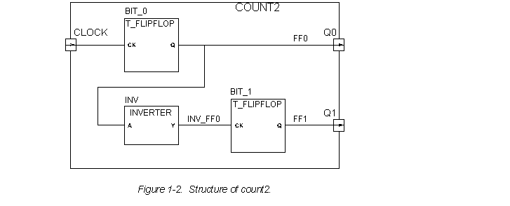
The two-bit counter might also be described as a circuit composed of two T-flip-flops and an inverter, as shown in Figure 1-2. This can be written in VHDL as:
architecture structure of count2 is
component t_flipflop
port
(ck : in bit; q : out bit);
end component;
component inverter
port
(a : in bit; y : out bit);
end component;
signal ff0, ff1, inv_ff0 : bit;
begin
bit_0 : t_flipflop port map (ck => clock, q => ff0);
inv : inverter port map (a => ff0, y => inv_ff0);
bit_1 : t_flipflop port map (ck => inv_ff0, q => ff1);
q0 <= ff0;
q1 <= ff1;
end structure;
In this architecture, two component types are declared, t_flipflop and inverter, and three internal signals are declared. Each of the components is then instantiated, and the ports of the instances are mapped onto signals and ports of the entity. For example, bit_0 is an instance of the t_flipflop component, with its ck port connected to the clock port of the count2 entity, and its q port connected to the internal signal ff0. The last two signal assignments update the entity ports whenever the values on the internal signals change.