A digital system is usually designed as a hierarchical collection of modules. Each module has a set of ports which constitute its interface to the outside world. In VHDL, an entity is such a module which may be used as a component in a design, or which may be the top level module of the design.
The syntax for declaring an entity is:
entity_declaration ::=
entity identifier is
entity_header
entity_declarative_part
[ begin
entity_statement_part
]
end [ entity_simple_name
] ;
entity_header ::=
[ formal_generic_clause
]
[ formal_port_clause ]
generic_clause ::= generic ( generic_list ) ;
generic_list ::= generic_interface_list
port_clause ::= port ( port_list ) ;
port_list ::= port_interface_list
entity_declarative_part ::= { entity_declarative_item }
The entity declarative part may be used to declare items which are to be used in the implementation of the entity. Usually such declarations will be included in the implementation itself, so they are only mentioned here for completeness. Also, the optional statements in the entity declaration may be used to define some special behaviour for monitoring operation of the entity. Discussion of these will be deferred until Section 6.5.
The entity header is the most important part of the entity declaration. It may include specification of generic constants, which can be used to control the structure and behaviour of the entity, and ports, which channel information into and out of the entity.
The generic constants are specified using an interface list similar to that of a subprogram declaration. All of the items must be of class constant. As a reminder, the syntax of an interface constant declaration is:
interface_constant_declaration ::=
[ constant ] identifier_list
: [ in ] subtype_indication [ := static_expression ]
The actual value for each generic constant is passed in when the entity is used as a component in a design.
The entity ports are also specified using an interface list, but the items in the list must all be of class signal. This is a new kind of interface item not previously discussed. The syntax is:
interface_signal_declaration ::=
[ signal ] identifier_list
: [ mode ] subtype_indication [ bus ]
[
:= static_expression ]
Since the class must be signal, the word signal can be omitted and is assumed. The word bus may be used if the port is to be connected to more than one output (see Sections 6.1 and 6.2). As with generic constants the actual signals to be connected to the ports are specified when the entity is used as a component in a design.
To clarify this discussion, here are some examples of entity declarations:
entity processor is
generic (max_clock_freq : frequency
:= 30 MHz);
port (clock : in bit;
address
: out integer;
data
: inout word_32;
control
: out proc_control;
ready
: in bit);
end processor;
In this case, the generic constant max_clock_freq is used to specify the timing behaviour of the entity. The code describing the entity's behaviour would use this value to determine delays in changing signal values.
Next, an example showing how generic parameters can be used to specify a class of entities with varying structure:
entity ROM is
generic (width, depth : positive);
port (enable : in bit;
address
: in bit_vector(depth-1 downto 0);
data
: out bit_vector(width-1 downto 0) );
end ROM;
Here, the two generic constants are used to specify the number of data bits and address bits respectively for the read-only memory. Note that no default value is given for either of these constants. This means that when the entity is used as a component, actual values must be supplied for them.

Finally an example of an entity declaration with no generic constants or ports:
entity test_bench is
end test_bench;
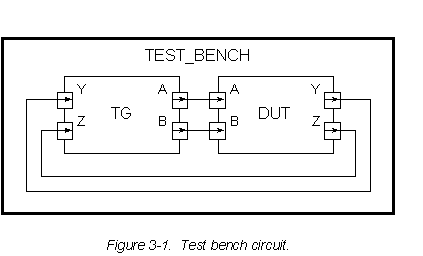
Though this might at first seem to be a pointless example, in fact it illustrates a common use of entities, shown in Figuer 3-1. A top-level entity for a design under test (DUT) is used as a component in a test bench circuit with another entity (TG) whose purpose is to generate test values. The values on signals can be traced using a simulation monitor, or checked directly by the test generator. No external connections from the test bench are needed, hence it has no ports.