

| <<< Ïðåäûäóùàÿ | Âåðíóòñÿ ê Áèáëèîòåêå |   |
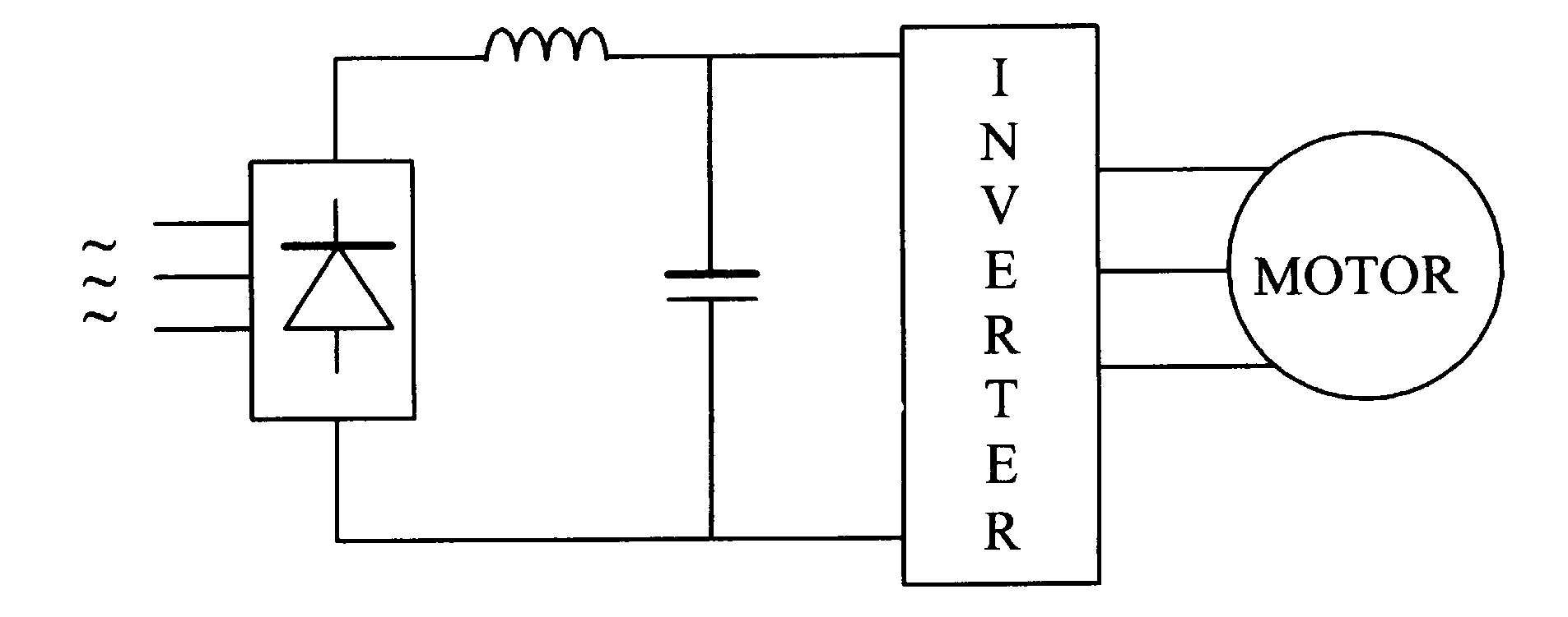
The torque equations 6.28, 6.33 and 6.34 of the foregoing sections indicate the motor behaviour of the synchronous motor under variable voltage and variable frequency supply. The analyses below assumes that three-phase sinusoidal ac supply of contnuously variable rms output voltage and frequency is available from an inverter, as indicated in the block diagram of figure 6.17.
Neglecting stator resistance R, the torque expression of 6.28 can be written as
 6.34
6.34
where ω1 = variable angular frequency, 2πf, (electrical) of the ac supply to the motor
V1= rms ac supply voltage to the motor at frequency f1
Xs1= synchronous reactance, 2πf1 Ls of the motor at the supply frequency.
Equation 6.34 implies that the developed torque is proportional to the applied rms voltage and its maximum value occurs for δ=90°. Since the mechanical speed is
This means that the same maximim torque is developed if the ![]() or
or ![]() ratio is maintained constant at all frequencies (speed). Note that this is very similar to the case of the induction motor. Near base speed, the motor back emf Ef and V1 are much larger than the voltage drop in the stator resistance, so that the above conclusion is quite valid near the base speed (base frequency). At low frequency, this drop may not be negligible.
ratio is maintained constant at all frequencies (speed). Note that this is very similar to the case of the induction motor. Near base speed, the motor back emf Ef and V1 are much larger than the voltage drop in the stator resistance, so that the above conclusion is quite valid near the base speed (base frequency). At low frequency, this drop may not be negligible.
Typical T-ω characteristics with variable voltage and variable frequency are indicated in the figure 6.18.
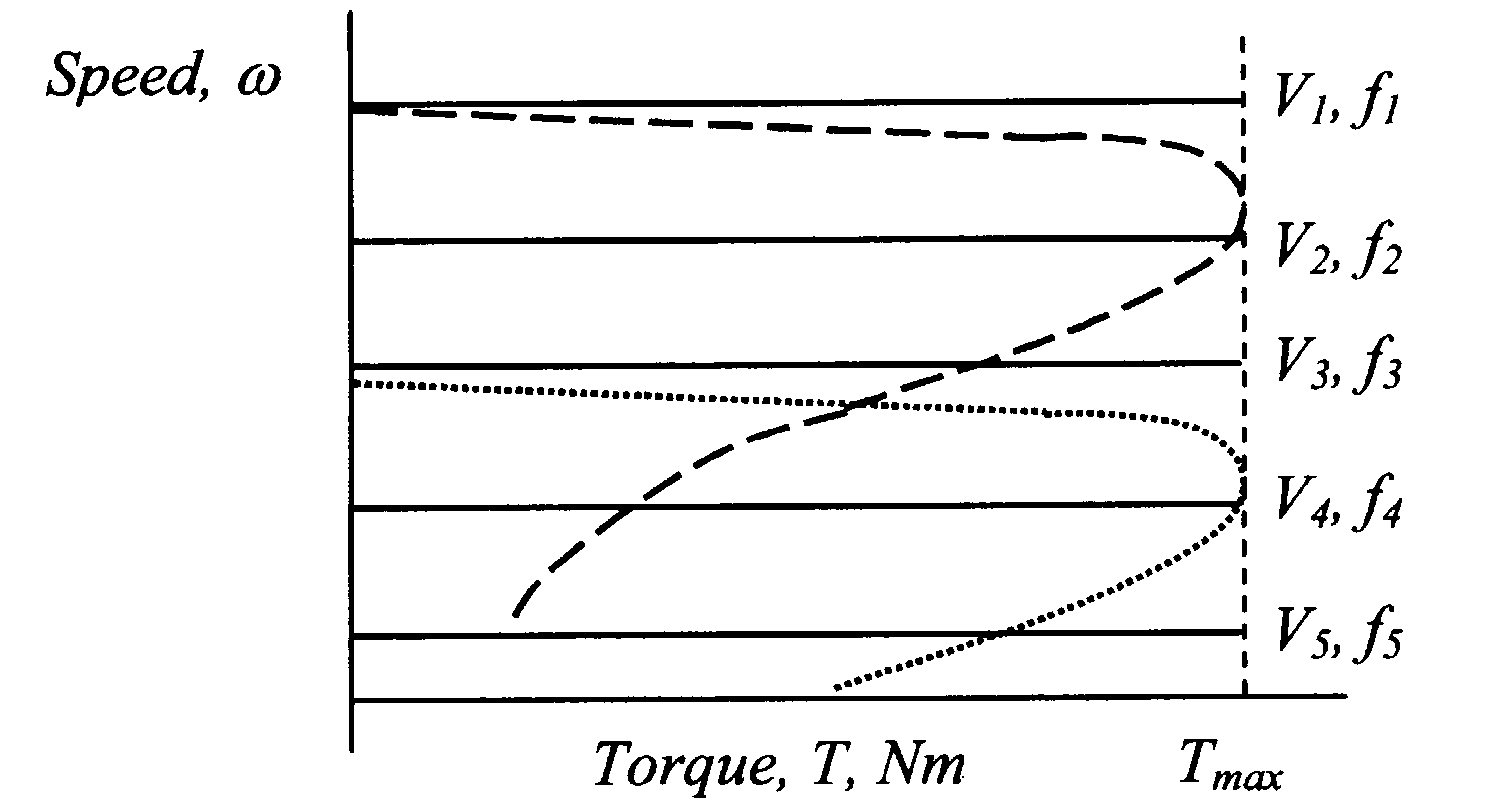
–– Synchronous motor T–ω characteristic with constant V/f ratio
---- Induction motor T–ω characteristic at base frequency
····· Induction motor T–ω characteristic with constant V/f ratio characteristic at ½ base frequency
By expressing the frequency variable f1 as
![]()
where f0, is the base frequency (50hz, normally), the torque expression of 6.34 can be expressed as
 6.35
6.35
The assumption of sinusoidal rotor flux distribution relates the rms value of the stator induced voltage Ef0 to the peak rotor flux density Br, frequency f0, and the number of stator turns Ns by Efo = 4.44f0NsBrA where A is effective area of each stator pole.
The stator flux linkage of each phase due to the rotor field is given by ![]() =BrA Wb.
=BrA Wb.
The ratio  , is thus proportional to the rotor flux. Thus
 6.37
6.37
Equation 6.37 states that if V/f
ratio is kept constant, the same torque is developed at a given δ and that the same maximum torque is developed at all speed. Note that this result is based on the assumption of negligible stator resistance.Note that the application of the balanced 3-phase sinusoidal voltage V1 to the stator windings also produce a revolving field, given by
V1 = 4.44f1NsBsA 6.38
where Bs is the peak stator flux density due to the stator supply alone. The developed torque may also be viewed as due to the tendency to align the stator and rotor fields Bs and Br respectively.
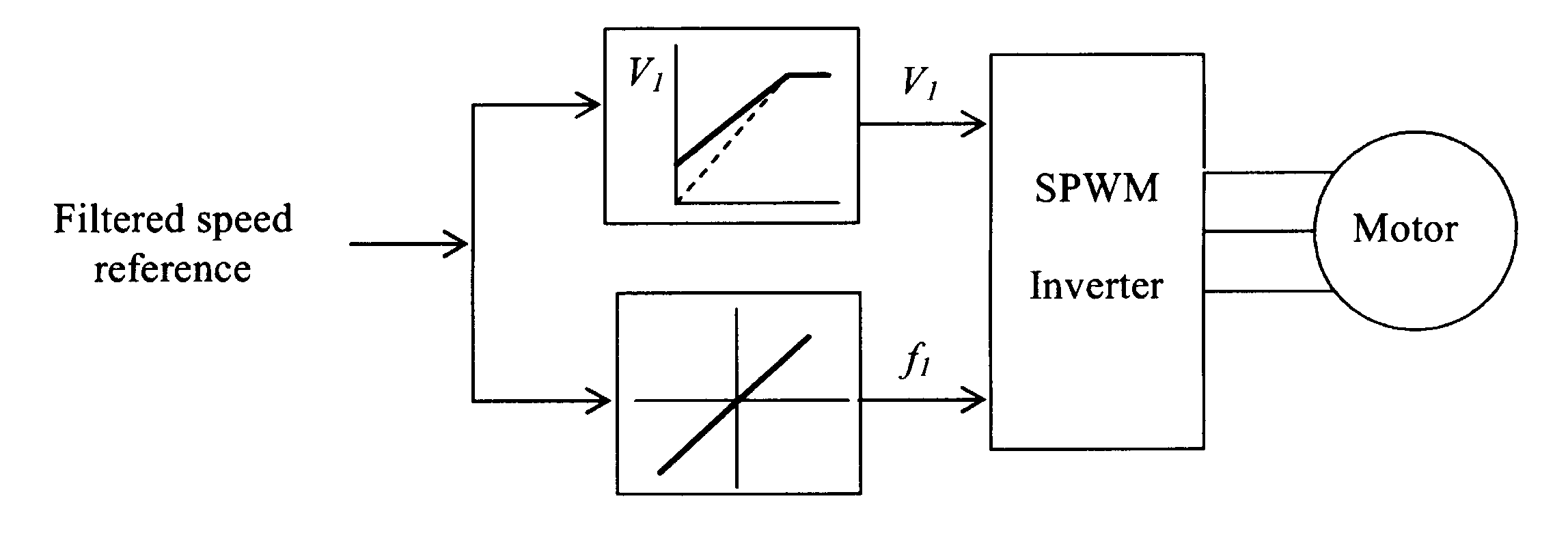
From the foregoing analysis it follows that an open loop speed controller should consist of a V/f controller as indicated in figure 6.19. The input frequency f1 of the supply frequency to the motor is selected according to the desired speed and the input voltage V1 is made proportional to f1. A sinussoidally modulated (SPWM) inverter may be used for this. The change of the speed reference must be such that the limiting
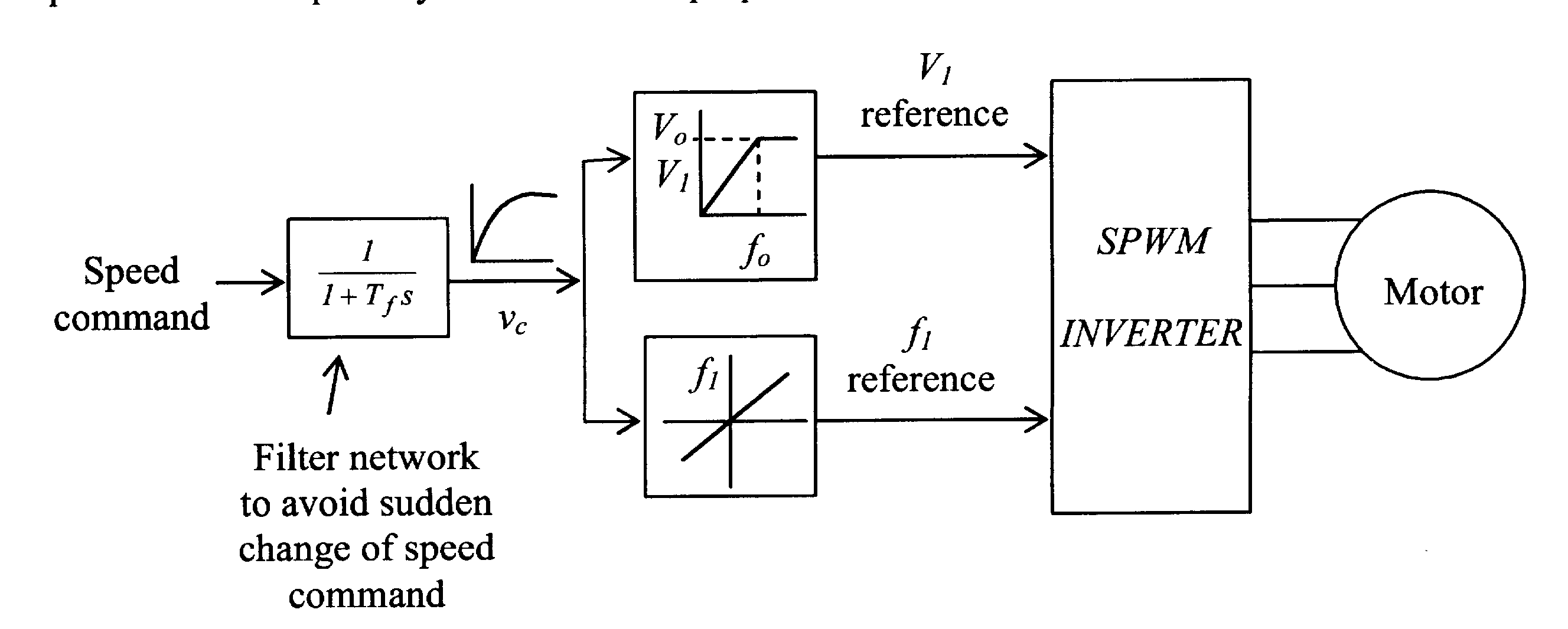
Normally, V1 is increased proportionately with f1, until the base frequency (speed) is reached. Thereafter, V1 is maintained constant at V0 which is the rated voltage of the motor. For operation above base speed, the frequency f1 only is increased. This, However, weakens the stator flux linkage, according to equation 6.38.
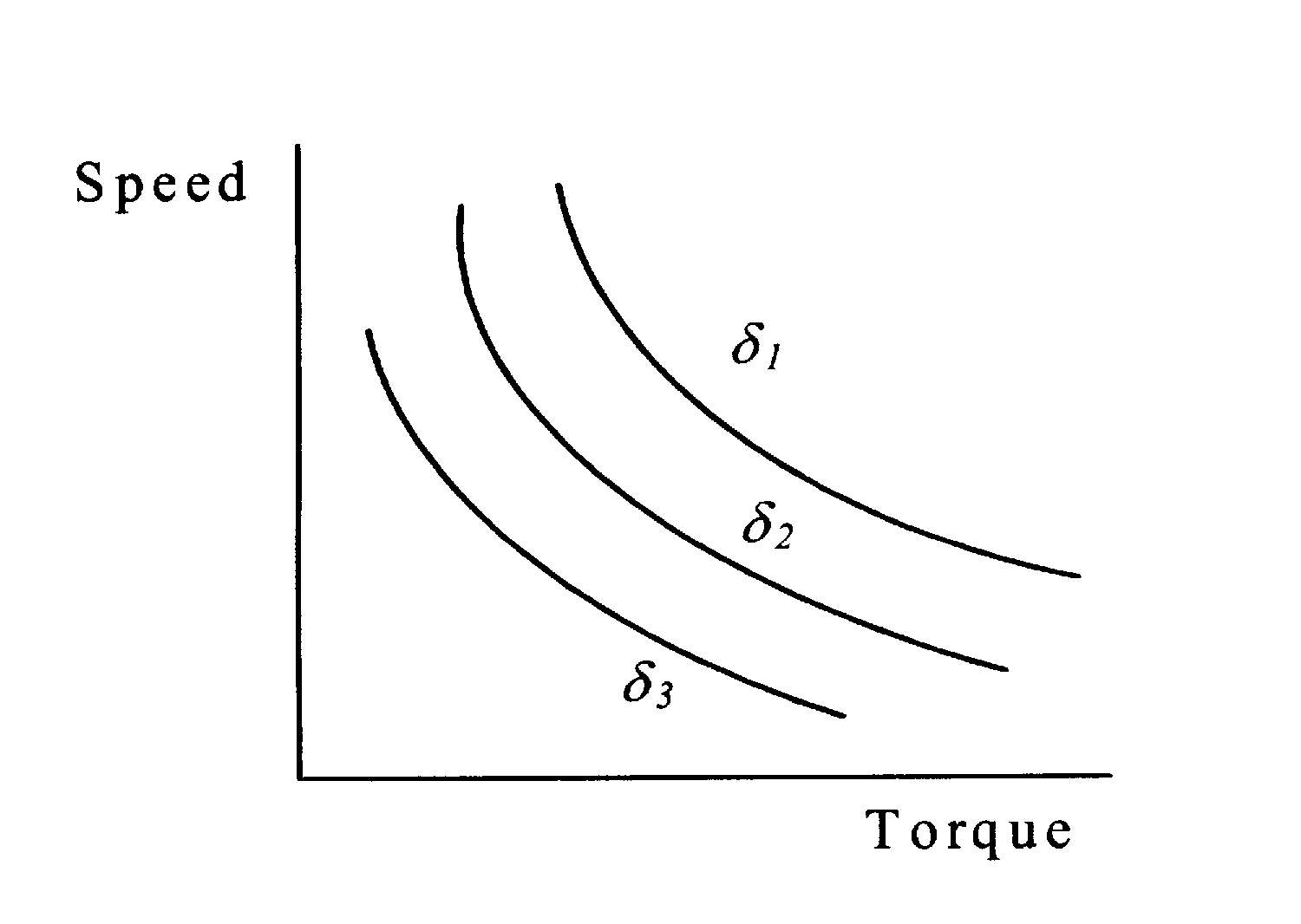
When a shaft mounted position sensor is available, the rotor flux linkage phasor of each phase winding can be reconstructed in phase and amplitude. (There are also other ways measuring the angle δ.). The maximum angle of the stator voltages V1a, Vlb, and V1c(i.e., δ1), with respect to the rotor flux linkage phasors for each phase can then be restricted to predermined values. The maximum developed torque is then given by
 6.39
6.39
The mechanical speed for any input frequency f1 is given by ![]() rad/sec. The maximum developed torque is determined by the limiting δ angle. If the supply voltage V1 (rms value) is also kept constant as is the case with operation above base speed, the motor will then develop a constant maximum-power characteristic given by
rad/sec. The maximum developed torque is determined by the limiting δ angle. If the supply voltage V1 (rms value) is also kept constant as is the case with operation above base speed, the motor will then develop a constant maximum-power characteristic given by
 6.40
6.40
Refer to the phasor diagram of figure below in which R is not leglected.
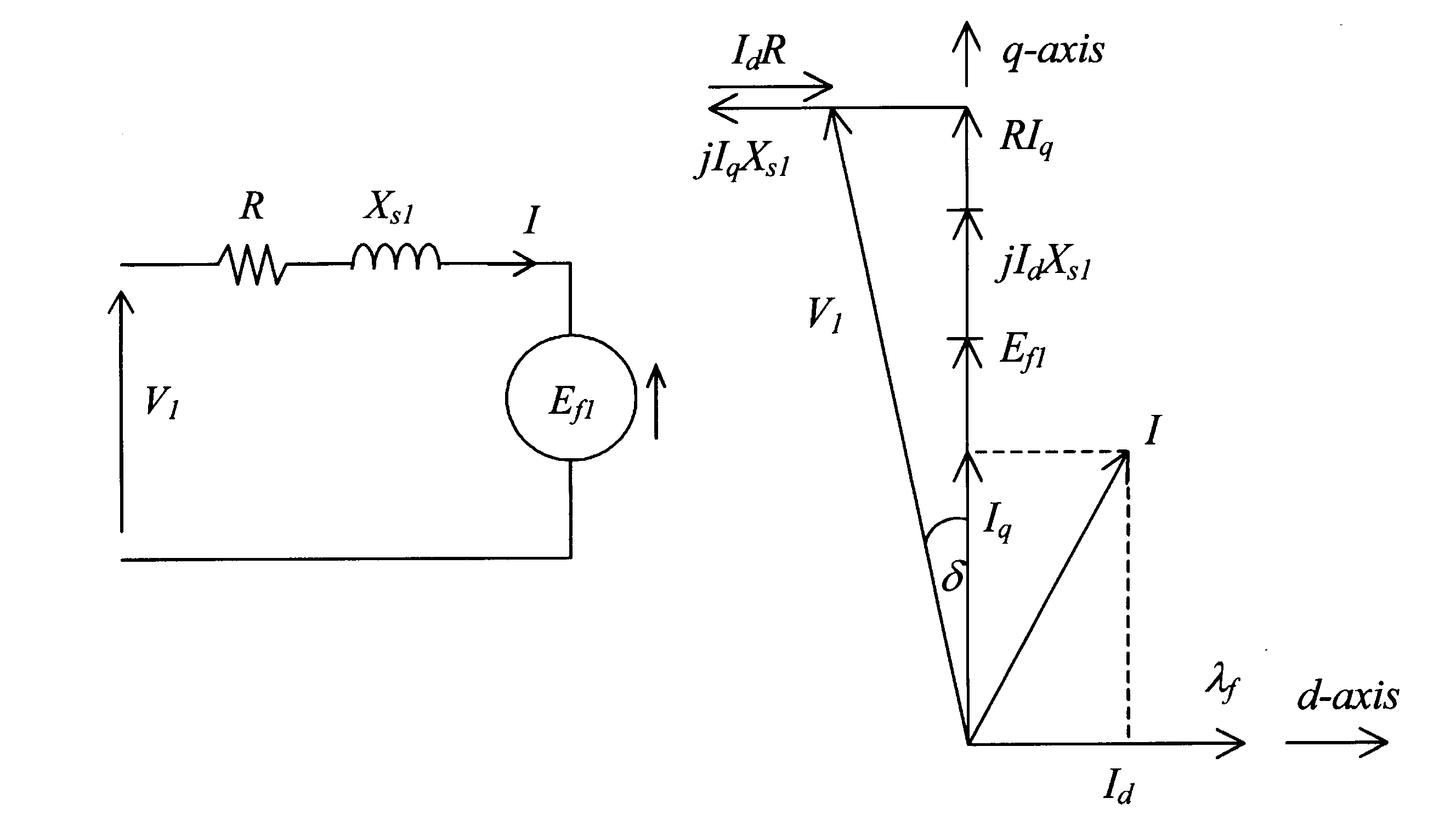
From the phasor diagram
![]() 6.41
6.41
![]() 6.42
6.42
Solving for Id and Iq from 6.41 and 6.42
 6.43
6.43
 6.44
6.44
The developed power is given by
![]() Watts/phase
Watts/phase
![]() Watts/phase
Watts/phase
 Watts/phase 6.45
The total developed torque for all three phases is given by
 Nm
Nm
 Nm 6.46
We now express the input frequency f1 in terms of the base frequency f0, as
![]()
so that Ef1 =
λEf0 =λe0V0, where![]()
where ![]() and Xs0 is the synchronous reactance of the motor at the base frequency (speed).
and Xs0 is the synchronous reactance of the motor at the base frequency (speed).
From 6.46, the developed torque is given by

 Nm 6.47
 Nm 6.48
By differentiating the numerator of 6.48 with respect to
δ and equating to zero, it can be shown that maximum torque will occur for a δmax given by 6.49
6.49
By using this δmax for a given λ from equation 6.49, the maximum torque the motor will develop at any speed can be found from equation 6.48. Even with a constant V-f drive, the maximum torque the motor will develop falls at low speed because of the voltage drop in the stator resistance. The T-ω characteristic of the motor in figure 6.22 clearly indicates the drop in the maximum torque the motor will develop at low-speed when the stator resistance is not negligible.
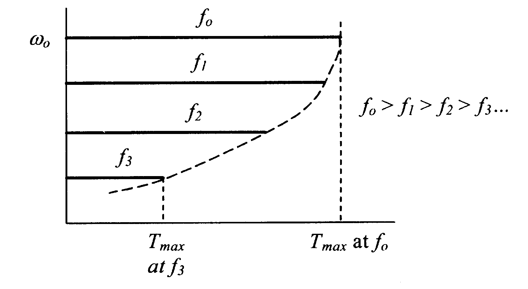
Note that near the base frequency, λXSO >>R and R≈0, so that the torque expression of 6.48 becomes the same as in 6.34.
At low frequencies, where λ≈0, Xs1 and Efl are both negligible. From 6.41 and 6.42
![]() 6.50
6.50
![]() 6.51
6.51
so that ![]()
Equation 6.52 implies that the zero-frequency voltage boost should be equal to
![]() 6.53
6.53
From 6.48, the developed torque at low frequency is given by
 6.54
6.54
Consequently, at low speed, Tmax will occur when δ= 0°
The zero-speed voltage boost (= R x lrated) the motor develops full rated torque at zero speed. The boost voltage has to be gradually reduced to zero so that at base speed, no voltage boost is applied.
By neglecting the stator resistance R, which implies operation of the salient-pole motor near the base or higher frequency, the developed torque from equation 6.33 is,
 Nm 6.55
As before, for any input frequency given by f1
= λf0,![]() ;
; ![]() ;
; ![]() ;
; ![]()
where the subscript o refers to base-frequency quantities. Using these, the developed torque is
 Nm 6.65
 Nm 6.57
Thus, if V1/f1 ratio is kept constant, the same maximum torque will occur at all speeds
An open-loop speed controller will be similar to the block diagram indicated in figure 6.19. If on the other hand, the load angle is limited to some arbitrary value δ1 and the supply voltage is also kept constant, say at the rated value V0, the torque equation 6.57 may then be expressed as
 6.58
6.58
Where
 6.59
6.59
 6.60
6.60
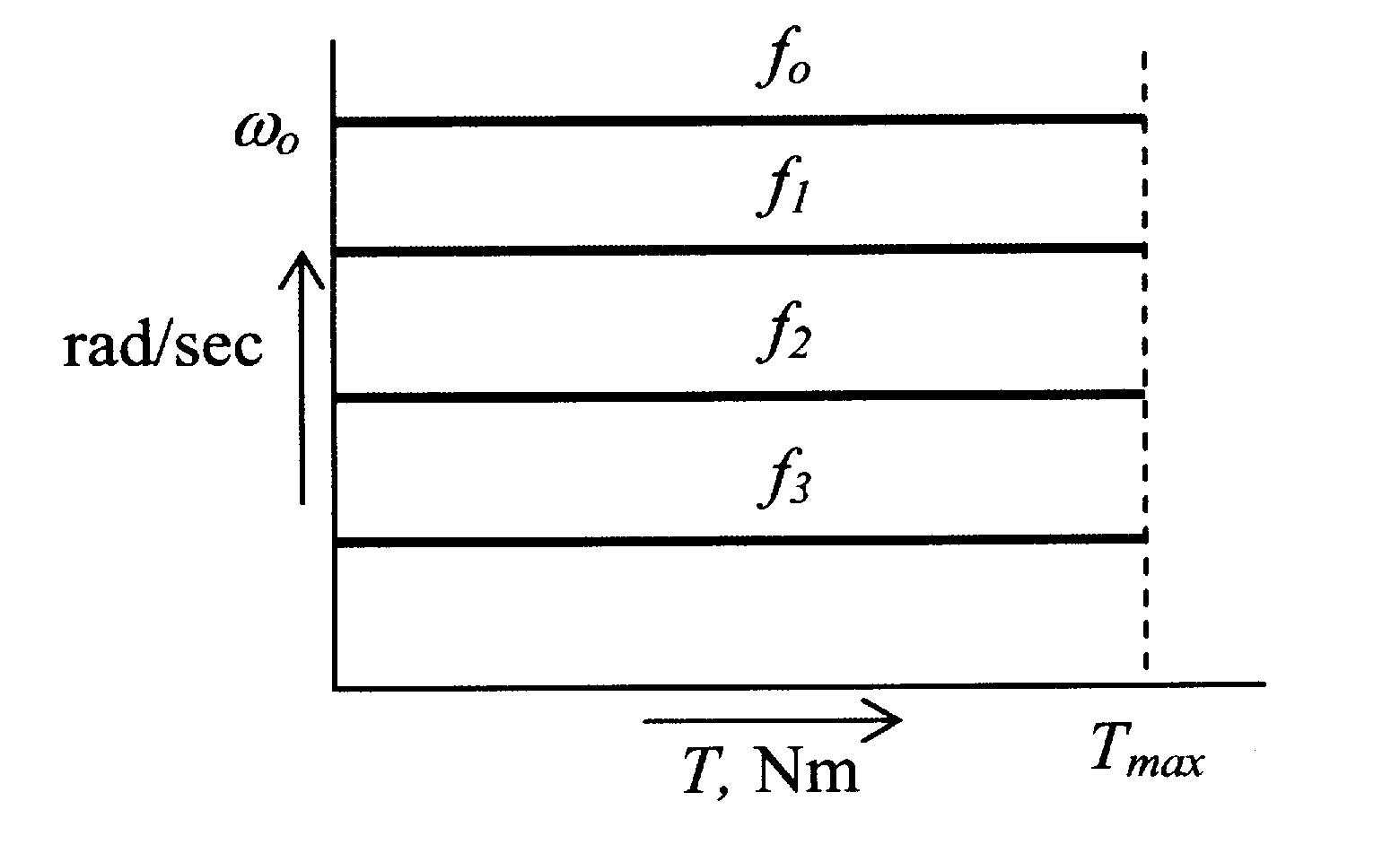
Equation 6.58 represents a constant power like
T–ω characteristics similar to those of section 6.4.1.2 (figure 6.20).At low frequency, the voltage drop in the stator resistance may not be negligible. Refer to the phasor diagram of the salient pole motor with R≠0, as drawn in the figure below.
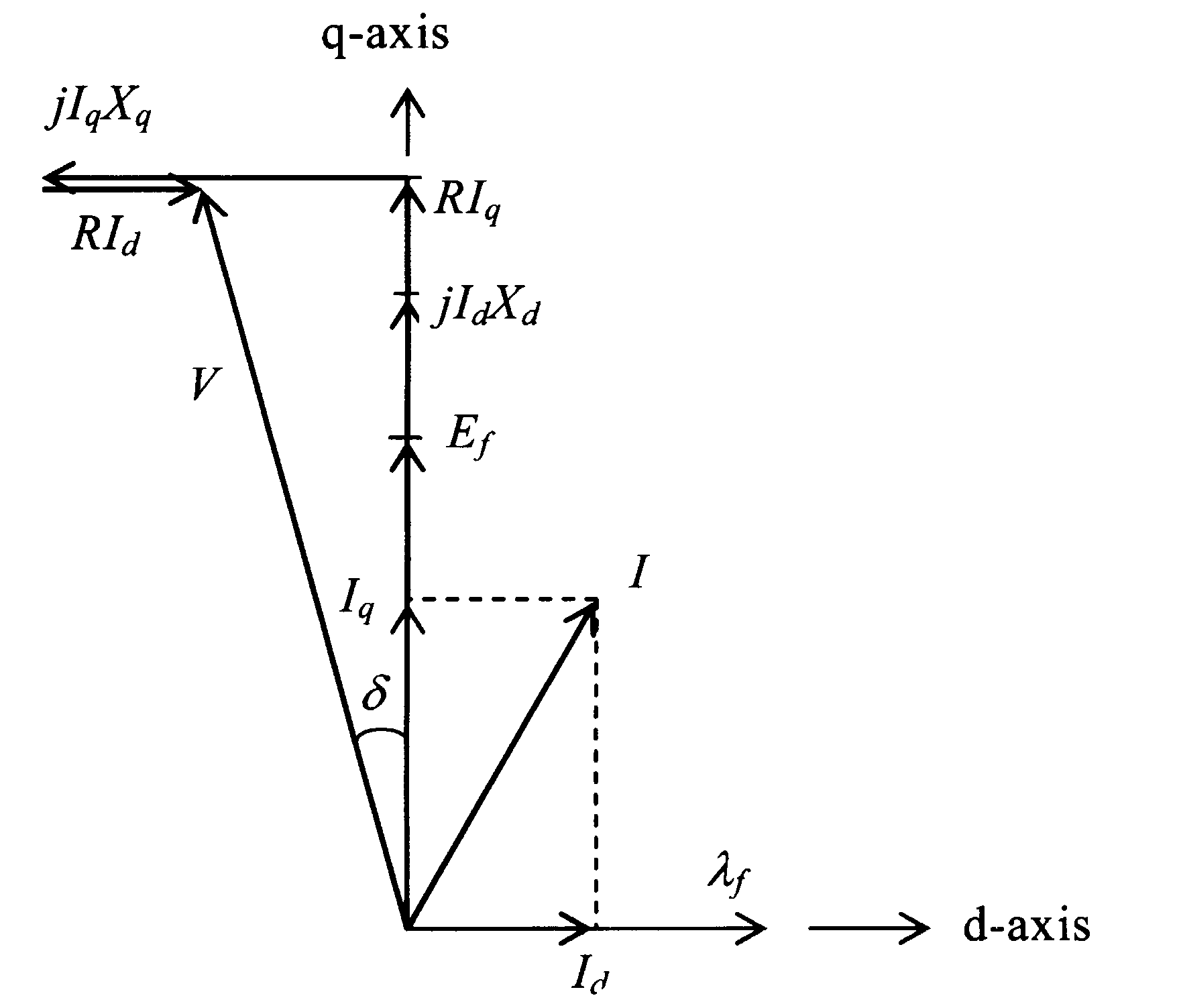
From the phasor diagram of figure 6.25
![]() 6.61
6.61
![]() 6.62
6.62
Solving for Id and Iq from 6.61 and 6.62
 6.63
6.63
 6.64
6.64
The developed power is given by
![]() Watts/phase
Watts/phase
![]() Watts/phase
Watts/phase
 6.65
6.65
Note at low speed, where
results are expected and imply that the zero-frequency voltage boost should be
![]() 6.66
6.66
The stator voltage VS frequency should thus be adjusted at low frequency as indicated by equation 6.66. This is also the case for the non salient-pole motor, as indicated by equation 6.53.
The developed torque from 6.65 is
![]() Nm
Nm
 6.67
6.67
For arbitrary supply frequency fl
=λf0, and input voltage V1 Nm 6.68
From equation 6.68, it may be seen that the maximum torque the motor can develop falls as the input frequrency (f1) or speed decreases, if the stater resistance R is not negligible. As before, the condition (δmax) for the maximum developed torque at any frequency (speed) can be found by differentiating 6.68 and then to zero. Tmax is then found by using the δmax in equation 6.68. The expression for δmax will not be attempted here for the sake of brevity. The T-ω characteristics for constant a V-f drive for various frequencies (speed) will be similar in shape as indicated in figure 6.26.
The maximum developed torque capability of the motor can be maintained by using voltage boost at low frequency, tapering it to zero in some fashion near base speed, as indicated in the block diagram of figure 6.23.
| <<< Ïðåäûäóùàÿ | Âåðíóòñÿ ê Áèáëèîòåêå |   |