Simulation of parallel transition processes in long electrical lines of computer circuits
TWO-PORT NETWORK
1.z, y, h, g - parameters
Literature

Different kinds of two-port networks.Quantity of shots - 6.Quantity of cycles of construction - 5. Weight - 19.8 Кб
TWO-PART NETWORK
A two-port network makes possible the isolation of either a complete circuit or part of it and replacing it by its characteristic parameters. Once this is done, the isolated part of the circuit becomes a "black box" with a set of distinctive properties, enabling us to abstract away its specific physical buildup, thus simplifying analysis. Any linear circuit with four terminals can be transformed into a two-port network provided that it does not contain an independent source and satisfies the port conditions.
1.z, y - parameters
The parameters used to describe a two-port network are z, y, h, g, and T. They are usually expressed in matrix notation, and they establish relations between the variables,

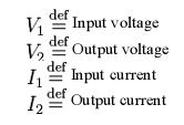
which are shown in Figure 1. These current and voltage variables are most useful at low-to-moderate frequencies. At high frequencies (e.g., microwave frequencies), the use of power and energy variables is more appropriate, and the two-port current-voltage approach that is discussed here is replaced by an approach based upon scattering parameters.
Though some authors use the terms two-port network and four-terminal network interchangeably, the latter represents a more general concept. Not all four-terminal networks are two-port networks. A pair of terminals can be called a port only if the current entering one is equal to the current leaving the other; this definition is called the port condition. Only those four-terminal networks consisting of two ports can be called two-port networks.
Impedance parameters (z-parameters)


Figure 2: z-equivalent two port showing independent variables I1 and I2. Although resistors are shown, general impedances can be used instead.
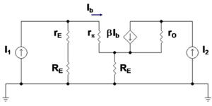
Example: bipolar current mirror with emitter degeneration.
Figure 3 shows a bipolar current mirror with emitter resistors to increase its output resistance. Transistor Q1 is diode connected, which is to say its collector-base voltage is zero. Figure 4 shows the small-signal circuit equivalent to Figure 3. Transistor Q1 is represented by its emitter resistance rE ? VT / IE (VT = thermal voltage, IE = Q-point emitter current), a simplification made possible because the dependent current source in the hybrid-pi model for Q1 draws the same current as a resistor 1 / gm connected across r. The second transistor Q2 is represented by its hybrid-pi model. Table 1 below shows the z-parameter expressions that make the z-equivalent circuit of Figure 2 electrically equivalent to the small-signal circuit of Figure 4.

Figure 3: Bipolar current mirror: i1 is the reference current and i2 is the output current; lower case symbols indicate these are total currents that include the DC components.

Figure 4: Small-signal bipolar current mirror: I1 is the amplitude of the small-signal reference current and I2 is the amplitude of the small-signal output current
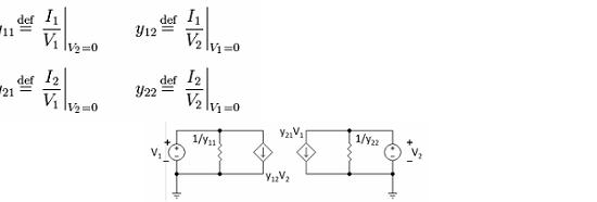
Admittance parameters (y-parameters)

where

Figure 5: Y-equivalent two port showing independent variables V1 and V2.
Although resistors are shown, general admittances can be used instead.
The network is said to be reciprocal if y12 = y21. Notice that all the Y-parameters have dimensions of siemens.
Literate:
1. Atabekov G. Theoretical bases electrical engineers, v.1, "Energy", М., 1964.
2. Beletskiy A. Bases of the theory of linear electric circuits."Connection",М.,1967.
3. Kalashnikov A. Electicity."Science",М.,1970.
4. German-Galkin B. Linear electric circuits."Korona print", СПб, 2002.
5. Blajkin V. The general of the electrical engineer."Energy", СПб, 1979.
6. Gershezon Е. Course of the general physics. An electricity and magnetism."Education", М, 1980.
7. Labusov А.N. "Parallel technologies". Electronic archive. http://www.spbcas.ru/cfd/techn/Parallel.htm
8. Мakashov А.V. "The analysis of efficiency of multistage multidot parallel methods of the decision of a problem of Koshi for the ordinary differential equations". Electronic archive.http://www.masters.donntu.ru/2005/fvti/makashov/diss/index.htm
9. Krukov V.A. "Distributed OS". Electronic archive. http://parallel.ru/krukov/index.html
10.Jim Ledin. "Modeling Dynamic Systems". Electronic archive. http://www.embedded.com/story/OEG20010304S0003


