Dynamic errors of current transformers and their correction
Introduction
Measuring current transformer - a transformer designed to convert the current to a value, easy to measure. The primary winding of current transformer is included in series with the measured alternating current, and the secondary includes instrumentation. The current flowing in secondary winding current transformer is proportional to the current flowing in its primary winding.
Current transformers are widely used for measuring electric current in the relay protection power systems, due to which they are imposed high demands on accuracy. Transformers current measurements provide security by isolating the measuring circuit from the primary circuit with high voltage, often amount to thousands of volts.
The secondary winding current transformer always loaded. Load resistance is strictly regulated requirements for the accuracy of the transformation ratio. A slight deviation of the resistance of the secondary circuit of nominal leads to a change in conversion error and possible deterioration of the measurement qualities of the transformer. The significant increase in the load resistance creates voltage in the secondary winding is sufficient for Insulation transformer, which leads to the output of a transformer failure, and poses a threat to life staff.
Practical relevance is to evaluate the errors introduced by instrument transformers. In the passport data for instrument transformer accuracy class is indicated that allows us to estimate the error in static mode at a constant or slowly varying loads. In evaluating the non-sinusoidal and the current oscillations is necessary to assess the dynamic errors.
Scientific relevance is to develop a method for estimating the error and its correction.
Scientific position: a method for the synthesis process of changing the primary current, the novelty of which is to use dynamic model of a measuring transformer for determining the dynamic error and its correction.
Dynamic errors of current transformers and their correction
Instrument transformers are working in the field of linear characteristics of the "primary current i1 – secondary current i2", therefore, the processes in them are described by linear differential equations. For brevity, we restrict ourselves to first-order equation.

where s - the Laplace operator, k - transformation ratio, T - time constant of the transformer and the measuring circuit. In this case we have the transfer function.

amplitude - frequency function (AFF)

phase-frequency function (PFF)

where ω – angular frequency of the measured sinusoidal signal.
The time constant can be determined empirically or calculated - on the transformer equivalent circuit. In the absence of information, it can be roughly estimated by the allowable angular error Δφ, which is contained in the directories under ω1=100π rad/s and is measured in angular minutes.
Equating (AFF) to Δφ, obtain:

which takes into account that the angular moment is 60 times greater than one radian.
For example, for transformers with accuracy class 0,2; 0,5 and 1% normalized error values ±10°, ±40° and ±80°. Given that arc second is 60 times greater than a radian, according to obtain the desired time constant: 9,3; 37 и 74мкс
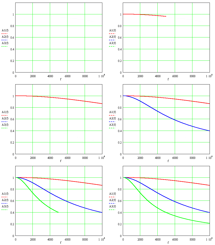
At pic.1 shows AFF for these values the time constant, where f=ω ⁄ 2π denotes the frequency of the measured signal: А1(f), А2(f) and А3(f) – for Т=9,3; 37 and 74 ms.

Picture 1. Amplitude - frequency functions of current transformers.
At nominal frequency 50 Hz AFF, multiplied by k, hardly differs from unity: 0,999996, 0,99993 and 0,99973, while at the greatest frequency of 2000 Hz harmonics accounted for the differences are more important: 0,993, 0,907 и 0,732.
To obtain the desired undistorted process enough to each ordinate the process i2(t) add correction factor Ti'2. Correction can be performed in real-time pace, adding to the measuring circuit forcing-link of the first order with a parameter T. Error correction by the accuracy of differentiation. If the recorded current schedule is approximated differentiable function, then the error does not. For illustrations in table 1 presents data on the amplitudes I2 and phases ψ2 harmonics of the current arc earth fault in a network of 6 kV isolated neutral, which was measured using current transformer with accuracy class 1%.

Currents were expressed in arbitrary units relative to the amplitude of the first harmonic. The values of the frequency characteristics calculated for T=7.4·10-5 s.
Adjusted parameters of the harmonics:

The relative error of measurement of amplitudes and phases of the harmonics in percent

In the study of random processes, for which the notion of harmonic loses its meaning, the error statistical characteristics estimated the spectral density of the recorded process or its correlation function - using the transfer function of transformer

Dynamic infelicity of transducers mode settings
Also in the automation of technological facilities for the control of the profile used primary converters (PC).
Each PC is a dynamic system, linear working range. Therefore, the process .gif) output
PC differs from the actual y(t). Dynamic error depends on the parameters of the PC and the type of process is recorded. The purpose of
is the estimation of errors and their correction.
output
PC differs from the actual y(t). Dynamic error depends on the parameters of the PC and the type of process is recorded. The purpose of
is the estimation of errors and their correction.
PC modeled part of the second order with time constants T1 and T2 a first order with time constant T. In the latter case, you can use all the results for the second-order level, putting them T1=T and T2=0.
Processes in the PC described by the differential equation

Amplitude and phase frequency functions (AFF and PFF)

where ω – angular frequency.
Difference in the processes can be clearly seen on the example, when measured by the unit function, but T1<2T2.
Denoting  , we process

Which not only differs from unity, but has an oscillating component. If the process is periodic, it is presented as a Fourier series. Let the harmonic order n with the basic angular frequency ω1 has amplitude cn and phase φn. Parameters of the harmonics, which are calculated on the process will be different:

Since the ω=0 AFF is equalunity, and PFF - zero, the mean value yc determined without error.
For a periodic process

Non-periodic process described by the spectral density S(ω) in the frequency range ω from 0 to infinity.

Integrating this density gives the variance

For example, for a random process with density

which has a parameter α, integration gives


As can be seen, the relative error does not depend on the variance process, but is determined through the parameter α and time constants of PC.
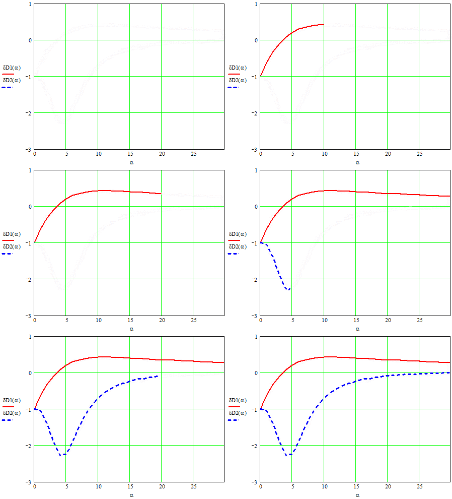
Figure 2 shows the error variances for the time constants.

Picture 2 dependence of the error variances of α
We now turn to methods of correction of dynamic error. Known here is the process of .gif) , on
want to restore the actual process y(t). Accuracy of reconstruction depends on the calculation of derivatives.
, on
want to restore the actual process y(t). Accuracy of reconstruction depends on the calculation of derivatives.
Real processes .gif) no breaks, so in some cases they can be
approximate analytic expressions are differentiated. Then the process of being built without errors.
no breaks, so in some cases they can be
approximate analytic expressions are differentiated. Then the process of being built without errors.
Certainly the processes .gif) defined as a sequence of coordinates with a small step in discrete time.
Use of computer operators of differentiation provides sufficient accuracy recovery process y(t).
defined as a sequence of coordinates with a small step in discrete time.
Use of computer operators of differentiation provides sufficient accuracy recovery process y(t).
Periodic process can be rebuilt and the harmonic:

In this case, differentiation is not necessary, but there is a known problem with the definition of amplitudes and phases of harmonics, as well as the number of harmonics, which must be considered. Thus, correction of dynamic errors can significantly reduce the requirements to the dynamic characteristics of transducers mode settings.
Conclusions
Conclusions will be formulated after conducting experiments.
Литература
1. Бессонов Л.А. Теоретические основы электротехники. Изд. 6-е, перераб. И доп. Учебник для студентов энергетических и электротехнических вузов. М., «Высшая школа», 1973. 752с.
2. Попов Е.П. Теория линейных систем автоматического регулирования и управления. – М.: Наука, 1989. 301с.
3. Электрические измерения // Под ред. В.Н. Малиновского. – М.: Энергоатомиздат, 1985.416с.
4. Теория автоматического управления // под ред. А.А. Воронова. - М.: Высшая школа, 1977, ч.1. - С. 303.
5. Вентцель Е.С. Теория вероятностей. - М.: Наука, 1969. - С.576.
6. Ермилов А.А. Основы электроснабжения промышленных предприятий. – М.: Энергоатомиздат, 1983. – 208 с
7. Трансформаторы тока / В.В. Афанасьев, Н.М. Адоньев, Л.В. Жалалис и др. – Л.:Энергия, 1980
8. Справочник по электроизмерительным приборам; Под ред. К. К. Илюнина — Л.:Энергоатомиздат, 1983


