
Abstract
Content
- 1 General review of work
- 1.1 Theme actuality
- 1.2 Review of literature and existing solutions
- 1.3 Purpose and objectives of work
- 1.4 Expected scientific novelty
- 2 Main part
- 3 Conclusion
- 3.1 The list of main results
- 3.3 Perspective of future work
- Links
- None
1 General review of work
1.1 Theme actuality
Nowadays, telecommunication systems which made due the Software Defined Radio (SDR) technology become very popular. SDR is a program computation complex which able to make digital signal processing in real time such as modulation, demodulation, coding and decoding. These capabilities are significantly simplify the realization, implementation and support for technologies which, use radio channel.
From OSI (Open System Interconnection) model standpoint SDR technology represents universal program platform for radio channel technologies, which implementing in physical level and is the fully independent from numerous wireless technologies. This is achieved by software signal processing, that's why realization of modulation and demodulation algorithms does not require intervention into hardware and helps to avoid unnecessary financial costs and at the same time increasing flexibility of system. Radio channel and digital signal processing domains are docking by the analog-to-digital converter (ADC) (Fig.1).

Figure 1 – Radio path of the SDR system
Because the modern standards of wireless communications have a high carrier frequency this is not possible to make direct sampling in way to restriction that are imposed by ADC, which performance in most cases does not exceed 500 MSPS (Millions Samples Per Second). To solve this problem in a chain of successive transformations of SDR receiver injects special front-end, which provides down-conversion to zero-IF frequency. This action helps to decrease requirements to performance of ADC and Digital Signal Processing. With this downconversion problem of image channel appears, which inharent to all direct conversion receivers (Fig.2).

Figure 2 – Image problem in direct conversion receivers
Because in this case problem of image rejection cannot
be solved with preselecting filter, such as in the superheterodyne receiver, analog path designing in quadrature oscillator and lowpass
filters way, which providing I/Q components formation of complex signal [1–3].
Thus formed signals arrive to synchronously working ADCs and then to DSP.

Figure 3 – Model of forming I/Q-components in SDR-receiver

Figure 4 – Impact of I/Q-imbalance to image channel appearence
[animation, number of frames – 13, repeat cycles – 7, size – 78kB]
If there is an amplitude and (or) phase imbalance between the I/Q components, image channel entering to the bandwidth of regarded main signal and not completely suppressed. This leads to the fact, that there is a mutual penetration of the upper and lower sidebands is observed. In this situation one sideband serves as the noise comparing to another one. This leading to decreasing signal to noise ratio (SNR) and increasing Bit Error Rate (BER). It should be noted, that the cause of the imbalance is the imperfection of SDR analog elements, which are the sources of amplitude and phase errors.
1.2 Review of literature and existing solutions
For nowadays, there are few methods existing, which have been proposed in opposition to this negative challenge. Among them – the static balancing on one frequency, at several reference frequencies within the range of received frequencies, dynamic balancing for frequency of the received range, assuming that the imbalance is the same for them.
The simplest of the considered methods in the literature are methods based on the calibration signals using. Their essence is to ensure that the receiving channel SDR-system is disconnected from the antenna and to it's input arriving the special signal, whose parameters are known a priori. After passing the the front-end and ADC, the observed realizations of signals comparing with expected. Based on this information the solution about image channel and imbalance parameter takes place. The main disadvantage is that during calibration time communication system must work to stop, so in practice more popular is the dynamic approach.
An example, M.Windisch proposed the method of dynamic estimation of I/Q-imbalance parameters based on the theory of Blind Signal Separation. In his paper the author considers the receiver with a low intermediary frequency, estimating the degree of mutual penetration by special factors K1 and K2. Imbalance descrypted by matrix of parameters and it's compensation reduced to finding inverse matrix, which is multiplied by the observed signal realizations [4].
Another approach have been proposed by S.W. Ellingson. The idea of it is that in the bandwidth of receiving signal selects single harmonic component. Further, considering it's successive transformations the author receives a corrective matrix that multiplied by channel signals I and Q [5].
However, in many cases, these methods do not provide the desired result because of complexity their implementation, failure to evaluate actual imbalance, refundable or not sufficiently suppress the imbalance. Listed above determines the relevance of this research and it's purpose.
1.3 Purpose and objectives of work
Purpose – increasing the image rejection ration, in way using an advanced methods of I/Q-imbalance estimation and compensation
Main objectives:
- Create mathematic model of I/Q imbalance;
- Substantiate and develop method of I/Q-imbalance estimation;
- Analyze error estimation of amplitude and phase imbalance
1.4 Expected scientific novelty
Within the master's thesis advanced method and mathematical model of I/Q imbalance estimation have been proposed. Within method formulas for the I/Q imbalance estimation have been obtained and proposed, which based on the time domain observations of I and Q components. During the research have been made simulation with error computation of proposed method.
2 Main part
The signal at the input of the quadrature mixer can be represented as polyharmonic, consisting an infinite number of
harmonic components.
Frequency of harmonic i, which located in frequency axis higher than heterodyne frequency ωc denote ωi,
and it's phase and magnitude denote ai and φi .
Frequency of harmonic i, which located in frequency axis lower than heterodyne frequency ωc and symmetric
ωi relative to ωc denote ω-i, and it's phase and magnitude denote
bi и φ-i.
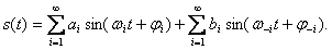
Given the notation adopted, signal at the input of quadrature mixer can be represented in the next way:
|
(1) |
This signal enters the branches of quadrature mixer, to which from quadrature heterodyne arriving signals shifted for 90 deg. What is more, this signals have an amplitude imbalance g and phase imbalance φ. This mathematic model is depicted on fig.3 and considers, that all amplitude and phase shifts, which take place in analog path of SDR are included into g and &phi parameters.
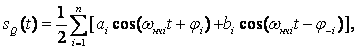
After mixing and lowpass filtering
on the exit of qudrature mixer we have I/Q signal, which consist only differential frequency components ωнчi=ωi−ωc

|
(2) |
|
(3) |
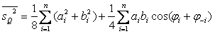
For next researching we must have mean of squares I and Q signals. As shown in literature [6], after averaging process (2) и (3) in infinity time interval the remaining terms give the following result

|
(4) |
|
(5) |
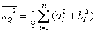
If we assume, that the phases and amplitudes of frequency components are distributed in a uniform law, the second term in (4) relative to the first can be represented such as infinitely small quantity, which in case of n →∞ can be omitted. A detailed explanation and proof can be found in the literature [6] . Considering this, expression (4) can be represented as follows

|
(6) |
In the same way, for expression (5) we obtain the same equations
|
(7) |
From the relations (6) and (7) we can easily find estimation of the amplitude imbalance

|
(8) |
Next, considering the mean value of the signals I and Q channels multiplication we can obtain
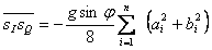
|
(9) |
From the relations of (9) and (7) follows

|
(10) |
Then, by replacing an amplitude imbalance by previously calculated it's estimation g, the expression for calculation phase imbalance can be obtained
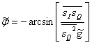
|
(11) |
On practice, the the value of phase imbalance does not exceeding few degrees (φ much less than π), that's why it's possible to calculate last one with the simplified formula.

|
(12) |
In example of using proposed theory simulation have been made. Simulation model includes analog path module, which corresponding with model depicted in Fig.3 and evaluator module, which have built accordingly the (8) and (11) formulas. In I branch an imbalance have introduced, with the g=1.05, φ=2 deg. parameters. As an input signal Gaussian white noise was used. In this model the Butterworth 5-order filter was used with a 100 kHz cut off frequency. The results of simulation is depicted on Fig.5 and Fig.6

Figure 5 – Process of magnitude imbalance parameter estimation

Figure 6 – Process of phase imbalance parameter estimation
During the simulation the amplitude imbalance value 1.046 is obtained, which very close to real-existing value 1.05. Obtained value of phase imbalance is 1.95 deg., when real-existing value is 2 deg.
The values of error computation have obtained too. For an imbalance parameters g=1.05 и φ=2 within cut-off frequency of lowpass filter, 100 kHz, mean of phase estimation error amounted 6 %, mean of amplitude estimation error amounted – 5 %. Reducing the cut off frequency leads to increasing the error estimates. To compensate imbalance you can use the algorithm described in [7] or the correction matrix, described in the literature, listed above.
Then for computing image rejection ratio formulas [8] were used. In our example level of image component before correction was −33 dB. After estimation and compensation the level of −53 dB was achieved and SNR ratio increases in 100 times.
3 Conclusion
3.1 The list of main results
During the work advanced method of I/Q imbalance estimation was designed. The simulation have been made, which allowing to consider obtained results is satisfactory. Thus, when the cutoff frequency low-pass filter was 100 kHz, the error in phase and amplitude estimations were a few percents.
3.2 Perspective of future work
In the future we plan to explore impact of filter's cut off frequency on the estimating parameters error. Also, the proposed method for estimating I/Q-imbalance is planning put into practice in the SDR receiver model. In addition, we plan to study bit error rate (BER) for different modulation types to draw conclusions about ability to use method in the nowadays wireless communication technologies. Plan to use the accumulated information to work on dynamic method for estimating frequency-dependent I/Q-imbalance with correction of the amplitude and phase errors separately for each frequency component.
Links
- R. Lyons Quadrature signals: Complex, but not complicated [Электронный ресурс]. – Режим доступа: http://www.dspguru.com/
- Р. Лайонс Цифровая обработка сигналов / Р Лайонс – М.: Бином-пресс – 656 с.
- С. Бахурин Выделение комплексной огибающей полосового радиосигнала. Квадратурный гетеродин. [Электронный ресурс]. – Режим доступа: http://www.dsplib.ru/
- M. Windisch, G. Fettweis Blind I/Q-imbalance parameter estimation and compensation in low-IF receivers [Электронный ресурс]. – Режим доступа: http://www.citeseerx.ist.psu.edu
- S.W. Ellingson Correcting I/Q Imbalance in Direct Conversion Receivers [Электронный ресурс]. – Режим доступа: http://www.ece.vt.edu/
- А.Г. Воронцов, А.А. Абраменко Оценка I/Q дисбаланса в радиотракте SDR-приемника / Воронцов А.Г Абраменко А.А – Серія: "Обчислювальна техніка та автоматизація". Випуск 172(20) / Редкол.: Башков Є.О. (голова) та ін. – Донецьк: ДонНТУ, 2012. – 224 с.
- О.О. Абраменко Розробка методики оцінки та компенсації I/Q-дисбалансу в радіотракті сучасних телекомунікаційних систем / Абраменко О.О – Сучасні проблеми радіотехніки та телекомунікацій «РТ-2012»: Матеріали 8-ої міжнар. молодіжної наук.-техн. конф., Севастополь 23–27 квітня 2012 р. / М-во освіти і науки, молоді та спорту України, Севастоп. нац. техн. ун-т; наук. ред. Ю.Б.Гімпілевич. – Севастополь: СевНТУ, 2012.
- I/Q Signal Mismatch Theory [Электронный ресурс]. – Режим доступа: http://paul.wad.homepage.dk/
Note
In the process of abstract writing the master's work hasn't been finished yet. Date of finish: December, 2012. The full thesis of master's work and materials according to the theme may be received from the author or his scientific advisor after the pointed date.