Contens
- 1. Trends in the industry
- 2. Description of the medium-section mill 390
- 3. Analysis of the structures of scissors for cutting steel
- 3.1 Classification of scissors for cutting steel
- 3.2 Description of the construction of scissors № 55 for cold rolling mill cutting 390
- References
1. Trends in the industry
Metallurgy – one of the oldest and most popular areas of human activity. Metal products are widely used in all areas of society due to their mechanical properties, in spite of its relatively high cost and complexity of manufacture. Almost all of the fundamental frames of machines, building construction, industrial designs and conventional domestic appliances, metal products, often the same essential element without which it essentially impossible normal work construction.
The increasing demand for metal products significantly influence the technology of metal blanks throughout the development of metallurgy. In an ever-increasing volume of orders quality metal for industry and construction, to the management of metallurgical plants, a number of tasks related to the improvement of the equipment manufacturing facilities, as well as the adoption of new, better and more cost-effective, methods of producing high quality metal.
At present, the world metallurgical practice in the integrated plan to distinguish between full-cycle (steel mills) and steel mini-mills. [1]. Organizations assume full metallurgical cycle production output after passing through all stages of production of the metal from iron-processing of raw materials (production of sinter), ending the production of liquid pig iron in blast furnaces, steel production (mainly in BOF), casting (usually on CCM or bars) as well as systems of rolling mills to produce certain types of metal. The main difference of steel mini-mills from companies with a full cycle is the use of metallic materials, mainly scrap. In this process of steel production based on modern electric arc furnaces.
In the works of A. Smirnov [1], A. Minaev [2] shows the main trends in the development of modern steel plants, highlights new approaches to the solution of certain problems of metal blanks and finished products. The use of casting and rolling units, which are combined in one unit a continuous casting machine and rolling mill, various combinations of main equipment – has enabled a new level in the development of relatively low-cost production of finished metal products, such as profiles, angles, circles, etc.
In addition to creating new mini-mills, continuously works on the reconstruction of production capacities of metallurgical plants with the full cycle [1], which have, in spite of ample opportunity to obtain the finished product, a number of shortcomings. The latter include the low flexibility of production under changing customer requirements, significant energy cost, complexity in coordinating various interrelated production facilities, the need for maintenance of numerous staff, and as a consequence, a significant increase in the cost of finished products. Therefore, to compensate for these shortcomings, the plants with the full cycle being taken to improve the installed equipment, or for a complete renovation of the existing production chains. The objectives of these improvements are to increase production flexibility, reduce the impact of human factors on the processes, and, not least, underline their positive qualities, such as: high volume and high quality of the finished product.
Technology for producing iron and steel, polished by years of practice, practically does not allow for large-scale upgrades to optimize production. However, the issue of unit-cast billets (blooms, slabs), not an end in metallurgy. The resulting castings arrive for processing at the mills, where there is production and the final product – Profiles of round, square, sheet, tube. The technology of rolling originally makes demands only to the properties of the metal itself to rolling, during, and after. Thus, there is significant room for new ideas to implement in the production of more sophisticated and efficient processing chain-cast billets.
Modern mill – a complex set of diverse machines located governmental solid lines up to 1000 m or more, in some cases, three or more bays of the building (Fig. 1.1, 1.2). Total weight of equipment to large mill is over 40 thousand tons of Rolling equipment – it's mostly cars with heavy supports to or pami large rotating parts (rollers, spindles, rollers, shafts, gears) as well as parts, reciprocating and curvilinear motion on a complex trajectory [3].

Figure 1.1 – Wire continuous mill

Figure 1.2 – Rolling continuous mill
The main manufacturers of rolling mills today – Siemens-VAI, Danieli, Sket, SMS-Demag.
One striking example of such a modern mill is 390 mill Makeyevka branch Enakievo Steel – one of the most advanced, the equipment and the organization of production, mills in Ukraine.
2. Description of the medium-section mill 390
Section mill 390 Makeyevka branch Enakievo Steel is designed to produce shapes of different sizes of the initial blank section 150x150 mm and 125x125 mm with a length of 12.0 m [4]. Total length of the mill is 500 m and consists of 18 work stands duo with individual drive, including the 8 horizontal and 4 vertical and 6 combined stands, as well as some other process equipment. The maximum rolling speed of the mill – 18 m/s, the estimated operating speed – from 2.3 to 17 m/s depending on profilerazmera rolled section steel. The mill is equipped with automatic control systems and management regimes rolling and the work of technological units, mechanisms and devices, and industrial cameras review invisible operator zones and sites, the production line, the monitors are mounted on the corresponding control stations.
Assortment mill very diverse provision for production of round (diameter’s 12..60 mm), square (14..45 mm), hexagonal (with diameters of the inscribed circle 14..48 mm) cross-sections, equal leg (25x25x3...4 to 63x3x4...6) and unequal (45x28x3...4 to 63x40x4...8) corners, channels (№ 5,0, № 6,5, № 8,0), etc. [4].
The high level of automation and the use of advanced technology allows to produce per hour to 120 tons of finished products. All production machines installed in the camp, do exactly its irreplaceable function, and are parts of one great chain, which has its source in the download section of blooms where prattsen cranes loaded cold billet grille to boot, and an end – in the areas of packaging and loading of finished steel.
Arrangement of mill equipment 390 Makeyevka branch Enakievo Steel is shown in Figure 2.1.

Figure 2.1 – Arrangement of mill equipment 390 Makeyevka’s branch Enakievo Steel: 1 – fixed focus, 2 – rack marriage preparations 3 – boot grille; 4 – roller table scales, 5 – dipping thrust, 6 – jogger, 7 – heating furnace, 8 – device for descaling, 9 – Tunnel thermostat, 10 – wire feeder to the 1st cage, 11 – roughing stands, 12 – Crankshaft -lever shears, 13 – intermediate group stands, 14 – crank-lever shear, 15 – finishing train, 16 – a device for measuring the geometrical sizes, 17 – area of accelerated cooling, 18 – two-system shears 19 – crank kroshitel, 20 – rack Rack, 21 – weighbridge, 22 – knitting machine, 23 – cross conveyor, 24 – fixed focus, 25 – Random length drive rod, 26 – Conveyor 1, 27 – Conveyor 2, 28 – dispenser, 29 – Cold flying shear cutting , 30 – straightening machine, 31 – petleregulyatory, 32 – a device to change the cages, and 33 – Breaking scissors 34 – car removal of blanks, 35 – Jogger, 36 – brakomotalka, 37 – wire feeder
Blanks prepared for the rolling mill, served prattsen crane (Figure 2.2) in stock blanks, and placed in a single layer on one of the two bootable arrays 3, from cams rack shleppera transported to shift the device.
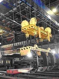
Figure 2.2 – Prattsen crane
Shifts the device blank piece sent to the feed roller conveyor, which are transported to the heating furnace (Figure 2.3). In the third section of the feeding roller blanks weigh in on the roller table scales 4, a fixed position workpiece weights provided on the site omits emphasis 5.
Faulty harvesting a supply roller conveyor fed to the opposite side of the furnace to a stationary anvil and one jogger passed by the lattice-rack 2.
Heating billets to rolling temperature produced in a methodical combination with water-cooled furnace 7 beams; feeding and unloading workpieces by using vnutripechnyh rollers. The oven is made on the basis of walking; pieces occurs by heating the gas.
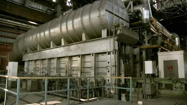
Figure 2.3 – Heating furnace walking beam
In an emergency situation in the mill associated with the termination of the rolling process, or, if necessary, unload the oven, heated workpiece unloading roller 34 is transported to a discharge roller conveyor in the opposite direction from the camp to the stationary anvil and pusher 35 are transmitted to the rack, which, after cooling, removed prattsen crane.
Hot same preparation, in contact with the main production line, enters the tunnel thermostat 9 (providing minimum temperature drop and alignment of the workpiece before the first stand), from wire feeder 10 is supplied in the first crate.
Before the first stand a bursting scissors Pendulum 33, which, when operational need or emergency situation occurs dividing cut off and prevent further harvesting in roughing. In this case, the movement of the upper and lower knives from the starting position to the contact with the faces of the workpiece is pneumatic, and their subsequent implementation in the metal – at the expense of pulling force the first stand.
Rolling of sections of the mill is in the three groups of stands (Figure 2.4):
- draft 11, consisting of one horizontal and one vertical stand 600, two horizontal and two vertical stands 440, with alternating horizontal and vertical stands in the group;
- intermediate 13, which consists of three horizontal and two combined stands 390, and a vertical stand 390; horizontal stand alternating with combined and vertical arrangement;
- finishing 15, consisting of two horizontal and four combined 390 stands, horizontal stands interspersed with combined.
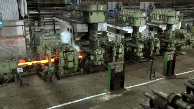
Figure 2.4 – Land stands
In the roughing and intermediate groups is rolling peal without tilting it with minimal tension between the stands, which automatically maintains a system of regulation of minimum tension.
On the crank-lever shear 12 and 14 (see Figure 2.5) after roughing and intermediate groups Prune front and, if necessary, the rear ends of roll, as well as emergency cutting-to-length parts.
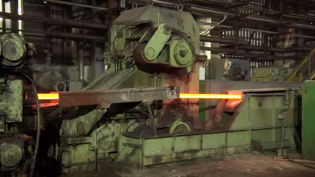
Figure 2.5 – The crank-lever shear
In finishing rolling is performed using the system loopcontrols. The value of the loop is maintained automatically loopcontrols 31 (Fig. 2.6) are used in the work of the photoelectric pulse encoders loop.
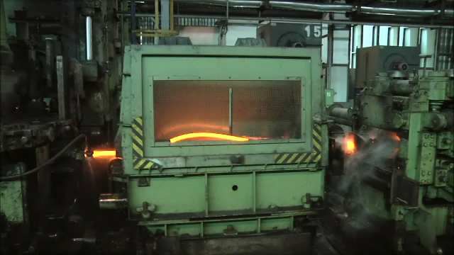
Figure 2.6 – Loopcontrol
Working stands are not used in the rolling process, are removed from the flow of the camp, and in their place are established special gutter.
Finished products, after controlling the geometrical size, transported to the accelerated cooling unit 17, reducing the increase of the strength properties of the metal.
In the production of profiles that do not suffer accelerated cooling sections instead of cooling tubes in a line camp to introduce the appropriate section roller.
Heat-treated or hot-rolled steel wire feeder is fed to the two-system stop-start scissors 18, which is cutting it on the rod of a given length, transported to the feeding roller table refrigerator.
Deceleration lanes is rolled on the receiving roller conveyor system, refrigerator double lift valves (partition walls and valves).
Refrigerator itself is a system of walking rails 20, cooled to shift rental in poperchennom direction upon receipt of blanks (Fig. 2.7).
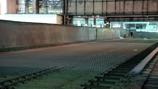
Figure 2.7 – Refrigerator with walking beam
Car rack after rack comes to the transfer device for collecting chains which are formed steel sections with a number of bars and the pitch layout, which are then transmitted to the outlet roller conveyor refrigerator.
On collecting roller table layer structural shapes on the end face of the front end by sinking all the way and delivered to the correct machine multistrand 30. Then, the head of the bed rolled after the right machine, goes on to the roller conveyor flying shear cold cutting 29 (Figure 2.8), which is cutting the front ends of the finished steel bars length. The correct machine and flying shears cold cutting work in the synchronous speed mode.
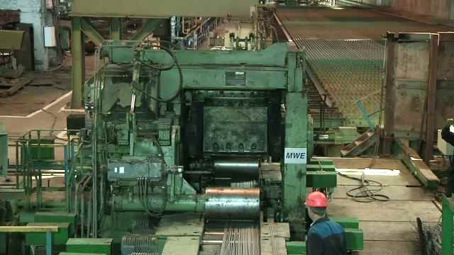
Figure 2.8 – Scissors cutting № 55 cold rolled
In the production of simple, not necessarily changes, the correct machine output from the stream and in its place introduced section roller. In this case, a layer of metal with diverter roller is fed directly to the flying shear cold cutting. Trimming all rolled layer and reveal a pair of scissors cutting cold rolled steel is in automatic mode.
Layers of bars finished length after cutting on flying shear cold cutting transported to the finishing area.
Then, depending on the profile and customer requirements, car transported by conveyors 26 and 27 in the area of packaging, which can be assembled into bundles or stacks with 22 knitting machines (Figure 2.9).
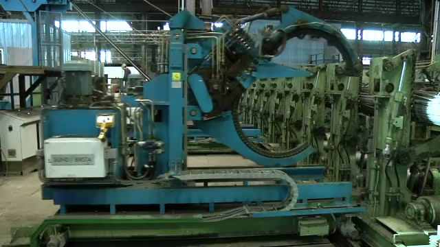
Figure 2.9 – Knitting machine
Package or stack of finished steel grille with the team passed hall crane to the storage of finished products or to load into the car.
All equipment of the camp – a unique, completely identical machines are not available, which is one of the characteristics of steel making. Emergency shutdown of even one of the machines leads to an emergency stop of a technological complex that, given the specifics of production, is a major concern, both economic and practical, because temperature of the heated metal reaches 1400 ° C. When designing the camp tried to consider the possibility of an emergency stop and consider various options for a quick exit from this situation. For example, in case of failure of one of the stands section rolling mill, it is possible to switch to another product mix, and continue rolling with the deletion of the faulty work shed.
But, despite this, the production line rolling mills have machines whose functions can not be replaced. Such equipment may include a heating furnace, refrigerator, as well as scissors cutting cold rolled steel.
In case of failure of one of the machines that are in the processing chain, the most serious challenge to create a hot rolling, located at that time on the line. And, if in the event of, for example, drive a heating furnace, billet, which managed to get to the lead-in roller conveyors, then continue to follow the established technology programs, without creating a hazard to persons, in the event of cold cutting scissors, or a refrigerator, located at the end of line, all the hot metal is on a roller table and in the stands. There are methods of shedding the main thread mill, but they are not effectively prevent emergencies.
Therefore, much attention is paid to the reliability of the equipment, by introducing a secondary machine and duplicate leads, as on the refrigerator mill 390. However, in the case of a pair of scissors cutting cold rolled, duplication and redundancy is impossible – the mechanism is synchronized with the correct machine and is located at certain distance from the last – to provide precise control of the length of rental and the quality of the cut. Any change in the relative position of the scissors and the right machine, even while maintaining synchronization, resulting in lower quality of cut, which is unacceptable. Installed at the end of the production line, they work during frequent start-stop and face regular shock, when Reza cooled blanks. In contrast to the rolling stands, the load on that are well known and hardly change [5], cold rolling scissors – much more unexplored element of the technological chain, because each mill steel cutting process is implemented in different ways, and, in accordance with this , information about the workload of carrying elements of scissors, mounted on the same camp, may not be applicable to similar design, mounted in a different product line.
In this regard, the provision and control of operational condition of scissors cold rolling – one of the most important challenges facing the HR mill.
3. Analysis of the structures of scissors for cutting steel
3.1 Classification of scissors for cutting steel
Cutting steel to length – is complex and demanding task. When metal cutting is a division of its in-plane shear cut knife. The knife has a front and side working faces with taper angle and cutting edge. Depending on the geometry of the cutting tool and the relative position of the front edges of knives, scissors, divided into four types [5].
Group 1 – scissors with blades parallel – cross cutting hot rolled square, rectangular and round on blooming, slabbing, billet and section mills.
Group 2 – guillotine with inclined blades. Used for hot and cold cutting sheets of fine profile packs.
Group 3 – disc shears – are discs and are designed to cross (rails, beams) and longitudinal (sheets) cut.
Group 4 – flying scissors – cut a strip along as it moves in the hot and cold.
Each group has a set of scissors variants, depending on the task. For example, flying shear may have a structure not just crank, but guillotine shears, in which blades are mounted on special rotating drums.
3.2 Description of the construction of scissors № 55 for cold rolling mill cutting 390
Cold rolled steel cutting scissors set the mill 390 Makeyevka branch Enakievo Steel, the type of geometry of cutting tools and the relative position of the front face of knives are the fourth group – flying shears. Depending on a given length of rolled profiles and rolling speed, cut occurs every 10-20 seconds.

Figure 3.1 – Schematic diagram of scissors cutting cold rolled
Figure 3.1 shows a diagram of scissors. Res is due to plane-parallel movement of supports 1, each carrying a knife 2. Knives, depending on the range of rolled, have a different view of the cutting edge, and can be changed if necessary. Fixed calipers at the knees tripodal crankshafts 3, and are free to rotate on them, thanks to loose fit. Plane-the knife provided by a system of levers rocker 4, connecting to the blade carriage.
Manual synchronization is carried out by means of shafts gear 5, with a gear ratio of 1:1. Cogwheel lower crankshaft also meshes with the drive gear 6. Shaft couplings through the last 7 is connected to a two-stage reduction gear 8.
The mechanism is driven by two synchronized, and, if necessary, overlapping, DC motors 9 capacity of 620 kW each. Engines, a clutch 10, connected to the gearbox, which has two input pinion shaft 11 and one output shaft 12. Input shafts drive the intermediate shaft 13, having engaged with the gear output shaft. All the gears are designed as helical. Overall gear ratio from engine to crank blades of 14.07.
Case of scissors is a three-component structure housings 14, which are located at the junction of crankshafts and gear shaft. Frame connected by tie rods M90 15.
Lubrication of friction by using oil station 16.
All components are constantly exposed to significant shear shock, so the demands on the quality of performance of all the components is very high. In the presence of the mechanism of any design defects or errors during installation, short-term impact of the dynamic forces provokes serious defects of basic and expensive elements.
Physically, at the time of the cut, there is a complete redistribution of forces in the mechanism by opening gaps gear and bearing support, which creates conditions for more dynamic impact. These processes have a negative impact on the state of structural elements, and require further research to monitor the technical condition of scissors.
Collapsible technical condition monitoring methods are uneconomical because they require complete closure of the scissors, and as a result, all the camp, which is unacceptable in continuous production. However, to obtain information about the state of the elements of mechanisms, there are methods of nondestructive testing. Most optimal and accurate method of them, at this time, is vibrometry. [6].
Temporary form (Figure 3.2) is the basis for the other methods, and includes recording of certain frequency range of vibration parameters time profile [8].
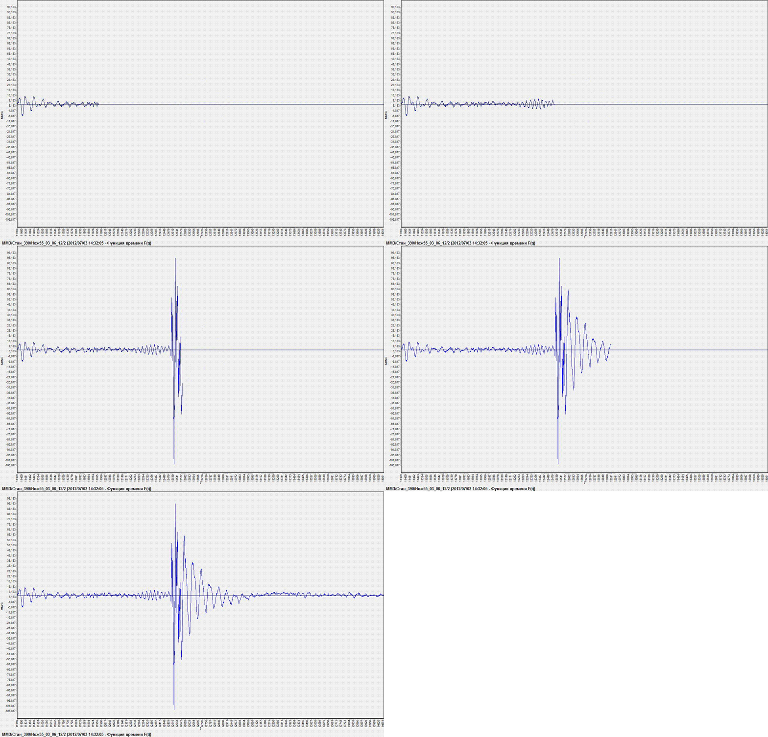
Figure 3.2 – Animated example of time series of the signal – shock process (made in mp_gif_animator, 111 kB, 5 frames, 0,7 s delay between frames, 4 cycling)
This master's work is not completed yet. Final completion: December 2011. The full text of the work and materials on the topic can be obtained from the author or his head after this date.
References
- Металлургические мини-заводы: Монография / М 54 Смирнов А.Н., Сафонов В.М., Дорохова Л.В., Цупрун А.Ю. – Донецк: Норд-Пресс, 2005. – 469 с.
- Минаев А.А. Совмещенные металлургические процессы: Монография – Донецк: Технопарк ДонГТУ УНИТЕХ, 2008. – 552 с.
- Торопов А.С. и др. Охрана труда при монтаже технологического оборудования. М. Стройиздат, 1987 г. – 286 с.
- Стан 390. Техническая документация
- A. И. Целиков, П. И. Полухин, В. М. Гребеник и др. Машины и агрегаты металлургических заводов. В 3-х томах. Том 3. Машины и агрегаты для производства и отделки проката. Учебник для вузов. – 2-е изд., перераб. и доп. – М.: Металлургия, 1988. – 680 с.
- Розенберг Г.Ш., Мадорский Е.З. и др. Вибродиагностика Монография. / СПб.: ПЭИПК, 2003. – 284 с.
- Кравченко В.М. Техническое обслуживание и диагностика промышленного оборудования. – Донецк: ООО
Юго-Восток, Лтд
, 2004. – 504 с. - Иориш Ю.И. Виброметрия М.: Государственное научно-техническое издательство машиностроительной литературы, 1963. – 756 с.
- Гольдин А.С. Вибрация роторных машин: – 2-е изд. исправл. – М.:Машиностроение, 2000 – 344 с.
- Основы теории механических колебаний, Капранова А.Б., Зайцев А.И. – Ярославский государственный технический университет, 1999. – 112 с.
- ГОСТ 20815-93
Машины электрические вращающиеся. Механическая вибрация некоторых видов машин с высотой оси вращения 56 мм и более. Измерение, оценка и допустимые значения
. - ГОСТ ИСО 10816-1-97
Вибрация. Контроль состояния машин по результатам измерений вибрации на невращающихся частях. Часть 1. Общие требования
. - Кравченко В.М., Сидоров В.А., Седуш В.Я. Техническое диагностирование механического оборудования: Учебник. – Донецк: ООО
Юго-Восток, Лтд", 2009. – 459 с.
- Биргер И. А. Техническая диагностика. – М.: Машиностроение, 1978. – 240 с.
- Артоболевский И. И., Бобровницкий Ю. Н., Генкин М. Д. Введение в акустическую диагностику машин. – М.: Наука, 1979. – 296 с.
- Голуб Е. С., Мадорский Е. З., Розенберг Г.Ш. Диагностирование судовых технических средств: Справочник. – М.: Транспорт, 1993. – 150 с.
- Коллакот Р. А. Диагностирование механического оборудования. – Л.: Судостроение, 1980. – 281 с.
- Борисенко В. Ф., Сидоров В. А., Мельник А. А. Подходы к оценке состояния электромеханических систем / Наукові праці Донецького національного технічного університету. Серія:
Електротехника і енергетика
, випуск 79. – Донецьк: ДонНТУ, 2004. – С. 23–26.- Ловчиновский Э. В., Вагин В. С. Эксплуатационные свойства металлургических машин. – М.: Металлургия, 1986. – 160 с.
- Патон Б.Е., О состоянии работ в Украине по технической диагностике промышленного оборудования, конструкций и сооружений. Доклад на 3-м расширенном заседании Технического комитета по технической диагностике и неразрушающему контролю (ТК-78) 27 мая 1999 г. Направление
Техническая диагностика
//Техническая диагностика и неразрушающий контроль
, 1999, №3. – С. 66-68.- В.В. Веренев, В.И. Большаков, А.Ю. Путноки, А.А. Корень, С.В. Мацко. Диагностика и динамика прокатных станов. Монография. Днепропетровск: IMA-пресс. – 2007. – 144 с.
- ГОСТ 30265-95
Варисторы. Метод испытания импульсной электрической нагрузки
.- ГОСТ 25275-82
Система стандартов по вибрации. Приборы для измерения вибрации вращающихся машин. Общие технические требования
.- ГОСТ 4.304-85
Система показателей качества продукции. Аппаратура и приборы для измерения вибрации. Номенклатура показателей
.- Дрейпер Ч. C., Маккей В., Лис С. Измерительные системы, Машгиз, 1960. – 784 с.
- Ушаков А. А. Виброизмерительная аппаратура, Изд. ВВА им. Н. Е. Жуковского, 1948. – 288 с.
- Кlotter К. – Messung mechanischer Schwingungen, Berlin, 1943.
- Messung mechanischer Schwingungen,
Richtlinien VDI
, 205—210, 1956.- Steuding H. Messung niechanischer Schwingungen, Berlin 1928.
- Герике Б.Л., Абрамов И.Л., Герике П.Б. Вибродиагностика горных машин и оборудования. Учебное пособие / Кузбасский государственный технический университет 2007. – 168 с.
- Седуш В. Я., Сидоров В. А., Ошовская Е. В. Контроль технического состояния металлургических машин по виброакустическим параметрам. Сб. научн. трудов. – Алчевск: ДГМИ, 2000. – Вып. 12. – С. 213–218.
- Сидоров В. А., Куватов А. В., Куришева Е. П. Анализ временных реализаций вибрационного сигнала / Научно-технический и производственный сборник статей
Вибрация машин: измерение, снижение, защита
. – 2005. – № 2. – С. 10–14.- Основы анализа данных и поиска неисправностей. By Glenn D. White, DLI Engineering Corporation. Пер. с англ. – Шейняк И. Р. / под ред. Смирнова В. А. Vibrashion.ru\Основы анализа.htm
- Преобразование Фурье и классический цифровой спектральный анализ. Медведев С.Ю., к.ф., м.н. [Электронный ресурс]. – Режим доступа: http://www.vibration.ru/preobraz....
- Электромеханические системы автоматизации стационарных установок (под общ. редакцией проф. Борисенко В.Ф.). – Донецк: ДонНТУ, НПФ
МИДИЭЛ
, – 2005. – 459 с.- Вэйвлеты в вибрационной динамике машин. А.И. Прыгунов [Электронный ресурс]. – Режим доступа: http://www.vibration.ru/wavelet....
- Добеши И. Десять лекций по вэйвлетам. Ижевск: НИЦ
Регулярная и хаотическая динамика
, 2001. – 464 с.- Диагностические параметры переходных процессов при оценке технического состояния электромеханических систем. Лытаев А.В., Сидоров В.А. // Автоматизація технологічних об'єктів та процесів / Матеріали ХIІ Міжнародної науково-технічної конференції аспірантів і студентів. – Донецьк, ДонНТУ – 2012, с. 441-443.
- Переходные процессы в электро-гидро-механических системах металлургических машин. Монография / Большаков В.И., Злобинский В.Е., Харлан Б.А., Цехнович Л.И., Яхно О.М. Днепропетровск: 2002. – 324 с.
Старт/Стоп
– измерение и анализ вибрации на переходных режимах, ОООИнкотес
[Электронный ресурс]. – Режим доступа: http://encotes.ru/....
