
Abstract
Contents
- Introduction
- 1. The mathematical description of the controlled system
- 2. Synthesis of system the subordinate speed control
- 3. Research results
- References
Introduction
Electric drive in the modern sense is a complex electromechanical system (EMS), for which the characteristic feature is the close relationship of processes in electrical and mechanical parts. The presence of elastic mechanical units at the relationship dramatically changes the properties of the drive as a whole and is the cause of vibrational effects in the dynamics. The vibrational components of motion the drive lead to a deviation transient processes from the prescribed technology and contribute to the growth of dynamic loads on the electrical and mechanical equipment.
Limitation of dynamic loads, an exact reproduction of the given laws of motion of the executive organs of the machine is a fundamental objective to design of the modern electric drive.
Usually limited stability to relations between the engine and the final controlling element of the mechanism, and sometimes between the individual elements of the mechanism due to structural features and requirements to reduce its weight and dimensions. Therefore, we wish to increase the stability of the structure can not always be met.
One of EMS, where the elastic vibrations have a negative effect on the performance of the drive mechanism is a bridge crane.
For bridge cranes with large span lengths amplitude elastic vibrations in a direction of movement of the bridge can reach several tens of millimeters, resulting in a significant increase in the mechanical stresses in some design nodes and greatly reduces the service life due to metal fatigue symptoms.
he question of the horizontal vibrations of the bridge crane beams hardly touched upon in the literature, despite their widespread use, and is a topical area of research.
1. The mathematical description of the controlled system
In the literature a lot of attention paid to the two-mass systems [1, 2], the dynamics of which largely affects only one free–running frequency. This model is applied to a system in which two large masses of interconnected elastic connection, the mass of which is neglected.
For the case when the trolley is shifted relative to the central point of the bridge, the bridge with a trolley can be represented in the form of three-mass system block diagram is shown in Figure 1 [3–5]. Figure 1 taken following notation: v1 , v2 , v3 - velocity points where the concentrated masses disposed m1, m2, m3; F1, F3 – forces generated by the drive motors of the wheels; l – a distance from the support to the truck; L – the length of the flight; F12, F32 – elastic interaction forces concentrated masses. Friction in a concentrated mass neglected, c12, c32 – elasticity coefficients.
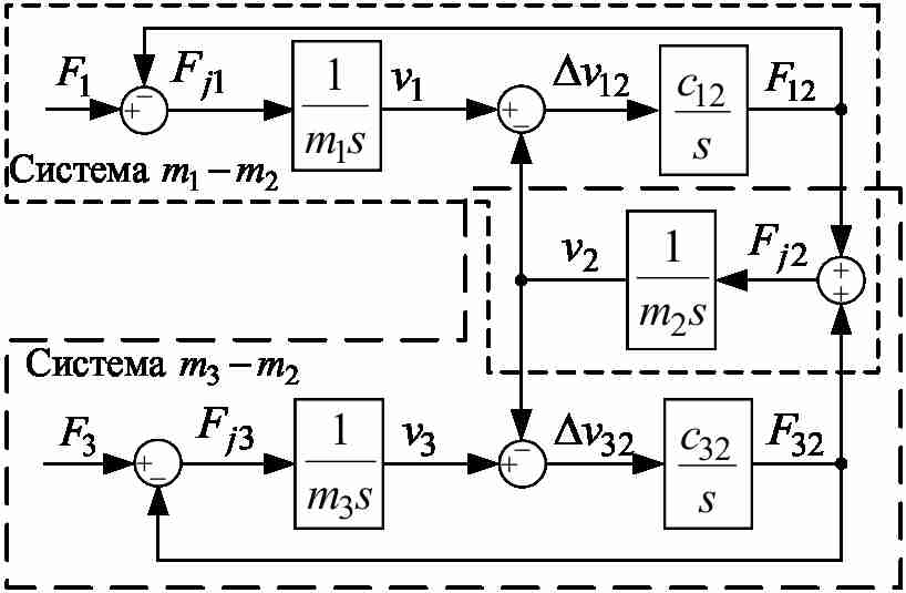
Figure 1 – Block diagram of three-mass system
First of all, we investigate object of regulation. The model of fig. 1 has a characteristic polynom:

where
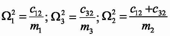
- frequencies of own elastic fluctuations moving masses;
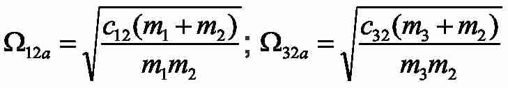
– frequencies of own elastic fluctuations autonomous two-mass systems 12 and 23;
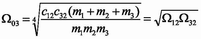
– compound root of a characteristic polynom considered three-mass system;
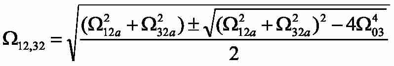
– frequencies of own elastic fluctuations of three-mass system.
The Transfer Functions (TF) from entrance forces to the dynamic effort influencing the second weight, have an appearance:
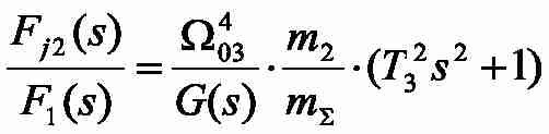
where
2. Synthesis of system the cascade speed regulation
The system has two electric drive, so you need to define two feedback gain and two time constants of the speed controller. Block diagram of the cascade speed control three-mass object is shown in Figure 2.
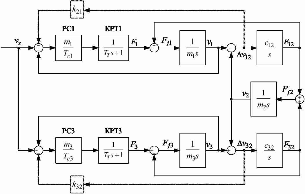
Figure 2 - Block diagram of the cascade speed control three-mass object
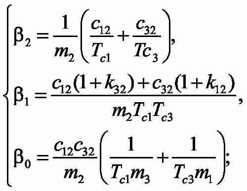
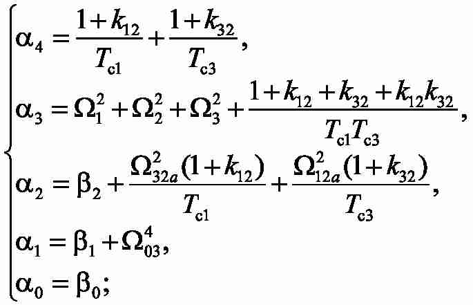
Optimize closed speed contures of magnitude optimum. For this we write the transfer function of the closed system of setting the speed to the speed of the second mass, which has the form:
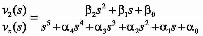
where:
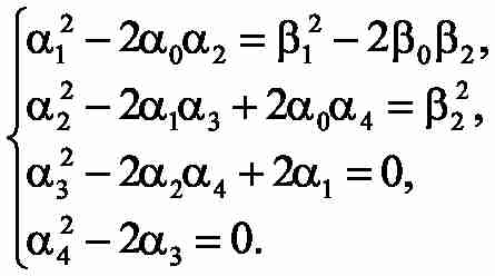
For the removed transfer function we work out the equations, providing achievement of MO [3, 4]. To define as unknown constants time Tc1,Tc3 , and coefficients of correcting feedbackk12, k32, it is necessary to solve system of 4 equations with 4 unknown:
3. Research results
We investigate the suppression of elastic vibrations. To do this, take the following parameters of the object of regulation m1=m2=m3=20, c12=4000, and c32=2*c12. The simulation results are shown in Figure 3. Parameters of the control system on the side calculated for these parameters: 1) m1=5kg, m2=m3=20kg, c32=2*c12; 2) m1=60кг, m2=m3=20кг, c32=2*c12. The simulation results shown in Fig. 3b and 3c, respectively.
Figure 3 - Transients in the subordinate regulation
(animation: 6 frames, 7 cycles, 230 kilobytes)
We see that in all three cases, the elastic vibrations are effectively suppressed. Quality transient slightly different in the signals of the drive force and speed overshoot is present up to 5-10%. Thus, we can conclude that the proposed method can effectively suppress the elastic vibrations in a fairly wide range of the ratio of the moving masses and the frequency of elastic vibrations.
Conclusion
The use of corrective feedback on the difference in the speeds of moving masses can effectively suppress the elastic vibrations in multi-mass systems. Depending on the ratio of the parameters of the original system, the quality we transients may slightly deteriorate, possibly withdrawn chenie deregulation or regulation time.
Final end: December, 2015. The full text of work and materials on a subject can be received at the author or his head after the specified date. This part of the paper the exclusively survey. Further work will be directed on a pilot study and completion of available results in the sphere of digital control systems.
References
- Борцов Ю.А., Соколовский Г.Г. Автоматизированный электропривод с упругими связями. – СПб.: Энергоатомиздат, 1992. – 288 с.
- Коцегуб П.Х., Баринберг В.А., Толочко О.И., Федоряк Р.В. Оптимизация двухмассовых систем регулирования скорости // Известия вузов. Электроме-ханика. – 1998. – №4. – С. 54-57.
- Толочко О.И., Палис Ф., Бажутин Д.В. Гашение горизонтальных упругих колебаний конструкции мостового крана / О.И. Толочко, Ф. Палис, Д.В. Бажутин // Електромеханічні і енергозберігаючі системи. Тематичний випуск «Проблеми автоматизованого електропривода. Теорія і практика» - Кременчук: КрНУ, 2012. – Вип. 3/2012 (19). – С. 336-339.
- Палис Ф, Толочко О.И., Бажутин Д.В. Анализ поперечных колебаний мостового крана при изменении положения тележки / Ф. Палис, О.И. Толочко, Д.В. Бажутин // Вісник Національного технічного університету «Харківський політехнічний інститут». – Харків: НТУ «ХПІ», 2013, №36 (1009). – С. 36-39.
- O. Tolochko, D. Bazhutin. Suppression of horizontal structural vibration of overhead crane in transversal direction given fixed trolley position // Науково-технічний журнал «Електротехнічні та комп’ютерні системи», 2013. - вип. 12(88). – с.14-22.
- Борцов Ю. А. Автоматизированный электропривод с упругими связями / Ю. А. Борцов, Г. Г. Соколовский – СПб. : Энергоатомиздат, 1992. – 288 с.
- Коцегуб П. Х. Оптимизация двухмассовых систем регулирования скорости / П. Х. Коцегуб, В. А. Баринберг, О. И. Толочко, Р. В. Федоряк // Известия вузов. Электромеханика. – 1998. – №4. – С. 54 – 57.