Abstract
Content
- Introduction
- 1. Theme urgency
- 2. Goal and tasks of the research
- 3. Gases separation technology
- 3.1 Gases separation principle
- 3.2 Classification of membrane air separation units
- 3.3 Analysis of the membrane unit producing nitrogen
- 4. Comparative analysis of the adsorption and membrane methods of industrial nitrogen production
- Conclusion
- References
Introduction
Study results of phenomena, which related to the selective transfer of gas molecules through solid (homogeneous) and microporous membrane with an inorganic or polymeric nature, success in the synthesis of polymers with a gas separation properties, the development of methods for the preparation of high-performance (asymmetric, composite, sputtered) polymer, metal and ceramic membranes, the creation of structures and methods of calculation of membrane apparatus and units are contributed to implementation method of the membrane gas separation in industry.
Prospects of gases membrane separation in the chemical industry are determined by simple hardware design process, reagent-free, cost-effective, long-term operation of gas separation membranes with unchanged its characteristics, the possibility of complete automation systems.
Gas membrane separation technology is used in processing of natural gas, oxygen-enriched air, the concentration of hydrogen ammonia synthesis purge gases, to create a controlled gas environment during storage of agricultural products, and many other purposes. The use of gas separation membrane is promising for the cleaning of exhaust gases.
1. Theme urgency
Atmospheric air is the raw material for producing industrial gases such as oxygen, nitrogen, argon, neon, krypton, xenon. The pace of the world's annual increase in production of these gases of the 1.2–1.4 times higher than the growth of any other types of products. Industrial production of these gases is carried out on the air separation units (ASU). There are three basic methods of air separation: cryogenic, adsorption and membrane [1].
In contrast to the membrane air separation units, cryogenic and adsorption ASU are complex technical systems, which including: equipment for air compression, cleaning it from moisture, carbon dioxide, volatile impurities; heat exchangers for cooling the air to cryogenic temperatures and heating product separation; fractionators and condensers-evaporators; cryogenic pumps [2].
Membrane separation of gas mixtures processes are refer to the new technological processes, which are now finding increasing application in various industries. Technological organization of the separation process in the membrane is simple and widely used on practice.
2. Goal and tasks of the research
The goal of the work consists of a substantiation of rational membrane units hardware design, which achieved the required purity of the final air separation products (nitrogen and oxygen) while minimizing energy and materials under given performance.
Main tasks of the research:
- An analysis of the theoretical foundations of the gas separation membrane in the cell.
- Justification of membrane module design, type and materials used membranes.
- Development of a mathematical model describing the operation of the membrane module.
- Analysis of the impact of various factors on the efficiency of the air separation membrane process and use this analysis to justify the selection of auxiliary equipment.
- The feasibility study of technical solutions.
Research object: membrane air separation process.
Research subject: hardware design process of membrane air separation.
The scientific novelty of the work is to develop an algorithm for hardware design study of membrane air separation process based on an analysis of interaction various schemes of membrane modules and analyze the impact of various factors on the efficiency of the process.
The practical significance of the work is to use the results of the work for reduce the energy and materials when making design decisions and implementation of industrial units for air separation.
3. Gases separation technology
3.1 Gases separation principle
Air separation on the membrane can occur without chemical transformations or with chemical transformations introduced via the membrane catalysts and enzymes. The membranes used as polymeric films, thin metal or ceramic plate, etc. and a liquid layer. Membrane module (Figure 3.1) provides separation of the feed stream F into two streams: permeate V is passed through the membrane, and the purge stream (retant) L is carried away to the next stage of separation or reset away. Technological organization of membrane separation process is simple and widely used on practice, for example in the preparation of nitrogen and oxygen from air [3].
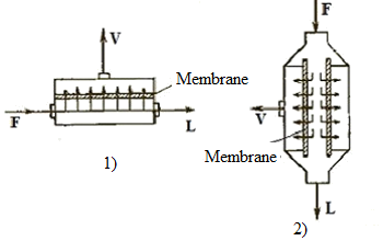
1 — flat camera; 2 — tubular
Figure 3.1 — Membrane modules schemes
The transport of matter through the membrane is effected by potential fields of different nature (pressure fields, temperature, concentration, gravity and electromagnetic nature). Streams of material through the membrane are diffusion, osmotic, ion, electrophoretic, etc. The mass flow in the membrane is oriented normally to the dividing surface. The driving force of the transport component is determined by the difference between the chemical potentials in the pressure and drainage canals which separated by a membrane. The rate of mass transfer through the membrane is varied by length and depended on the thermal and hydrodynamic parameters at the point of the flow or drain channel [3].
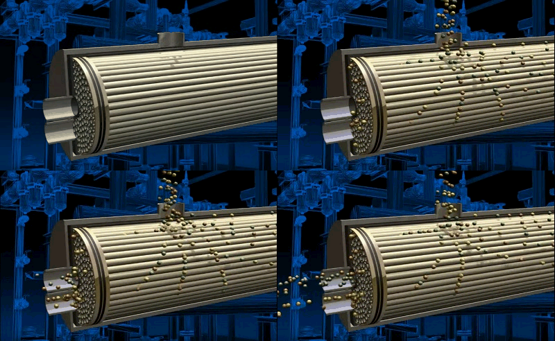
Figure 3.2 — Air separation process in tubular module
animation: 4 frames, 6 cycles of repeating, 143 kilobytes
In describing the process of mass transfer across the porous membrane different models of viscous flow and molecular flow are often used. Membrane pore structure is complex and often unknown, so it is necessary to consider the structure and pore sizes (equivalent diameter of the channel length, specific surface area, pore size distribution) for the proper application of flow equations in the calculating of gas membrane separation processes. Pore size for viscous flow must be sufficiently large comparing with the mean free path of the gas molecules [4].
3.2 Classification of membrane air separation units
Streams schemes in the membrane elements which forming the membrane in the assembly apparatus are showed on Fig. 3.3. Gas in the pressure and drainage canals can move as: 1 — forward flow, 2 — backflow, 3 — cross flow. Flat camera's and tubular modules (see Figure 3.1) are two main types of membrane modules by design features. In the modules by flat camera's type cross-sectional shape of the pressure and drainage canals closed to the square, and if there is no free convection than aspect ratio channel dimensions allow you to simulate the processes it as two-dimensional flow of gas from the selective suction or blowing. In the modules with tubular elements one channel has a circular cross section, and a gas flow in it can be considered axisymmetric; the second channel is formed by the outer cylindrical surfaces of adjacent membrane elements and the module case, it is implemented a more sophisticated model cylinders beam flow with different angles of attack [3].

1 — forward flow; 2 — backflow; 3 — cross flow
Figure 3.3 — Scheme of flow management in membrane apparatus
Membrane gas separation units are divided into single and multi-stage. Gas mixtures separation in the single-stage membrane units is used in cases where the membrane has a very high selectivity with respect to the extracted component. Single stage unit may include one or more membrane modules which connected in parallel, series or combined. Roughly the same amount of feed mixture with the same composition is supplied in each of the membrane modules, which connected in parallel. Obtained in each of the modules retentate and the permeate flows are discharged into the general collector (Fig. 3.4, 1). The advantage of this scheme is the ability to disable the part of the modules while reducing consumption of the feed mixture, that allows to keep constant the concentration of the resulting products. Such systems is easy to scale, that is to transfer the results of semi-industrial tests on large-scale industrial units. The main drawback of this scheme is necessity of careful control by the uniform distribution of the initial mixture into modules. This scheme is most appropriate to be applied for relatively small values of flow division ratio with using membranes, which has high permeability and high selectivity [4].
Gas losses into pressure channels by the direction of gas movement are reduced when membrane modules are connected in series (Fig. 3.4, 2). To provide the same gas velocity it is necessary to install modules with decreasing sizes in the course of gas motion. In units of this type we can may obtained permeates of different composition. They can be used in separation of multicomponent gas mixtures. Permeate of first modules is enriched components wich has the highest permeability permeate of latest modules – components with intermediate values of constants, a retentate – components with the lowest permeability. The disadvantage of this scheme is a relatively large flow resistance [4].
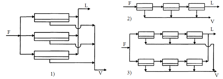
1 — parallel; 2 — serial; 3 — combined
Figure 3.4 — Schemes of units with a different arrangement of the membrane modules
Combined (serial-parallel) units are the most often used among single-stage installations in industrial practice. Schema of combined unit is showed on Fig. 3.4, 3. This case is mixed capability of the unit work under varying load by the source gas mixture with the capability of separating multicomponent mixtures.
The more membrane surface in the same module and the smaller units are integrated in one unit, the smaller the overall size and cost of the entire system and the more simple and reliable its operation. At the same time an application of large number of modules with the same size provides greater flexibility in the unit [4].
3.3 Analysis of membrane unit producing nitrogen
In Russia and the CIS development of membrane apparatus is associated with the creation of asymmetric polyvinylthreemethylsilane (PVTMS) membrane at the Institute of Petrochemical Synthesis named A. V. Topchiev and hollow polymer fibers at the "Khimvolokno" (Mytischi) [2].
Asymmetric membrane consists of a homogeneous active layer several micrometers thick porous substrate and 100–200 microns thick. Asymmetric membrane permeability is significantly higher than homogenous which had a minimum thickness of faultless several tens of micrometers because all permeate flow resistance is concentrated in a homogeneous thin layer. This allows to decrease surface area of the membrane unit polymer side by side preservation of the polymer selectivity, i.e. to decrease size and capital costs, and to make the separation process cost-effective [5].
The main advantages of membrane gas separation units:
- gas mixtures separation without phase transitions at normal temperature;
- ecological purity of membrane and separation products;
- flexibility of characteristics and fluidity of regulatory regimes;
- a short start-up time (1–2 minutes) and ease of maintenance;
- long service life (over 10 years).
Membrane units producing nitrogen are used to create an inert environment during storage and transportation of flammable liquids and fuel, storage machinery, smelting of non-ferrous metals, the polymerization process in an autoclave, purge cooling jackets turbine generators CHP, post-harvest handling and storage of grain, food packaging, the drilling operations in the oil and gas industry, in medicine carrying hypoxic etc.
The construction is based on the modular construction that allowed to replicate modules for creating units with performance from 1 to 500 m3/h and nitrogen content in the product of 98–99%. It is possible to reduce nitrogen content while increasing performance (for example, tuning mode of obtaining nitrogen with a 95% purity is increased a performance of 2 times) [2].
The air (F) is included in the unit (division level) producing nitrogen (Figure 3.5) and divided into two streams, which pass a difficult path and saturated permeate component — nitrogen (V). Then it's removed via the nozzle 1. Waste stream (L) is got in perforated pipe 5. The partitions 2 are set through different number of membrane elements. Most of elements are installed in the beginning, but their quantity are reduced by the direction of gas flow in the end [2].
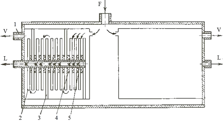
1 — nozzle; 2 — membrane element; 3 — partition; 4 — lining; 5 — perforated pipe
Figure 3.5 — Schematic diagram of the apparatus producing nitrogen
4. Comparative analysis of the adsorption and membrane methods of industrial nitrogen production
Nitrogen is widely used in various industries, such as: the creation of inert atmosphere in tanks with fire and explosive liquids; purging and testing of oil and gas pipelines; nitrogen fire fighting in coal mines; exploration of oil and gas wells, etc. There are three main indastrial methods of air separation to obtain a nitrogen, such as cryogenic (liquid air distillation), adsorption (oxygen molecules are retained in the molecular sieve pores, with following their regeneration in the adsorption units) and membrane process. Cryogenic method has the next drawbacks: high cost; the complexity of hardware design; operating complexity; explosion and fire; the presence of harmful emissions that pollute the environment and so this method is not considered for further analysis [6]. The various indicators comparison of pros and cons of adsorption and membrane units are presented in Table 4.1 [8].
Table 4.1 — Pros and cons of adsorption and membrane methods nitrogen production
| Adsorption units | Membrane units |
| 1. Achievable purity nitrogen | |
| Pros: Stable nitrogen purity is easy to be ensured at level up to 99.999%, which enables the use units of almost all production areas and non-production activities. | Cons: In most cases the attained nitrogen purity does not exceed 99.5%. To achieve purity higher than 99.5% the compressed air consumption and, consequently, the energy consumption exceed indicators of adsorption units. Therefore, the membrane nitrogen generator may be a cost-effective option only when the required level of purity gas is at 99.0 ... 99.5% or below. |
| 2. Sensitivity to vapors compressor oil | |
| Cons: The adsorbent needs to be protected from the compressor oil vapor. | Cons: The membranes are susceptible to damage vapor compressor oil, so in the compressor it is necessary to use synthetic oil, which lose less heavy hydrocarbon compounds. |
| 3. The sensitivity to humidity | |
| Cons: The presence of moisture vapor in compressed air causes a decrease of the adsorbent efficiency, in this connection it's necessary to set up the installation of compressed air dryers. | Pros: The presence of compressed air moisture vapor is not regulated and does not have a noticeable effect on the functioning of the most membrane manufacturers. |
| 4. Sensitivity to the compressed air temperature | |
| Pros: Adsorbents are insensitive to the temperature of compressed air both in terms of efficiency and with wear standpoint. Heated compressed air is not used. | Cons: The most membrane manufacturers are extremely sensitive to the compressed air temperature. To provide effective work, it's necessary to heat compressed air up to +40 ... + 55 ° C. |
| 5. Complexity regulation of nitrogen purity and performance | |
| Cons: To change the calculation of nitrogen purity and productivity is difficult. This requires careful adjustment of both the flow and pressure regulator settings, and a change of programmable parameters. | Pros: Nitrogen purity and performance are changed due to extremely simple adjustment with one flow control, which installed on the membrane outlet. |
| 6. Process stability | |
| Pros: Problems in work of regulators are unlikely and even if they are arised, they do not usually lead to jumps of gas purity. | Cons: Pressure or flow vibrations are more likely and may result in a drop of purity. |
| 7. Service term of adsorbent | |
| Pros: If compressed air is proper cleaned, than service life of the adsorbent is 10 ... 15 years or more. | Cons: Membrane inevitably and quickly wears out even if compressed air is proper cleaned. The service life of the membranes is typically about 5 years. |
| 8. The cost of working material (adsorbent and membrane) | |
| Pros: The adsorbent is cheaper than the membrane, as at relative terms comparing with the cost of the entire system, as well as at absolute value terms. | Cons: Membranes cost a big part of the unit price, and at absolute terms the membrane modules are also more expensive than the adsorption units with the same performance. |
| 9. The complexity of hardware design | |
| Cons: The design of the adsorption units is more complicated than membrane, and that means a greater likelihood of failures. | Pros: Simple design with a minimum of moving parts. |
| 10. The complexity of installation | |
| Cons: Adsorption units are badly fit for installation as part of containerized mobile nitrogen stations. | Pros: Membrane modules are well suited for installation in containers and operated in mobile nitrogen stations. |
The data is presented in Table 4.1 shows that both systems of producing nitrogen has advantages and limitations. But modern membrane units are the basis for the creation of non-waste technologies, their application can solve one of the major technical contradictions "industrial potential of growth" — "clean environment", as they "nonchemical". From this point of view membrane technology is the future [8].
The membrane separation is based on different air permeability (permeation rate) of oxygen, nitrogen and other air components through the membrane material. The volumes of oxygen and nitrogen (reduced to normal conditions) that pass through the membrane are defined by the formulas, respectively [7]:
Vo=Кo·S·ΔP·τ;
Vn=Кn·S·ΔP·τ;
where Кo and Кn — permeability coefficients of oxygen and nitrogen, respectively;
S — working area of the membrane;
ΔP — pressure difference before and after the membrane;
τ — time.
The physical meaning of the coefficients Кo and Кn is that they respectively indicate volumes of pure oxygen and nitrogen, which passed per unit time through a 1.0 m2 membrane at a pressure difference of 1.0 MPa. The numerical values of the coefficients are determined experimentally. The values of oxygen, nitrogen and other gases permeability coefficients (helium — He, neon — Ne, argon — Ar, krypton — Kr, xenon — Xe), which part of air are shown on the figure 4.1 with using logarithmic scale. Figure 4.1 shows that the oxygen permeability approximately twice the nitrogen permeability. The air separation membrane technology is based on these properties of oxygen and nitrogen [7].
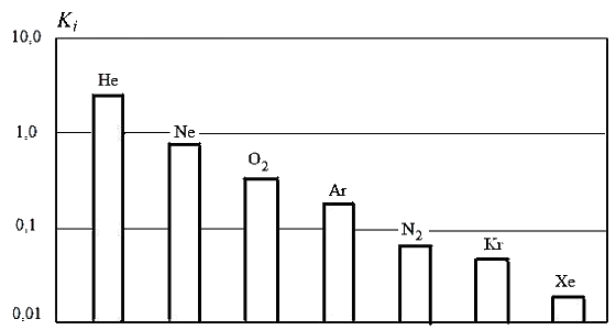
Figure 4.1 — Permeability coefficients of air components
Conclusion
Membrane separation of gas mixtures processes are refer to the new technological processes, which are now finding increasing application in various industries. Technological organization of the separation process in the membrane is simple and widely used on practice.
Asymmetric membrane consists of a homogeneous active layer several micrometers thick porous substrate and 100-200 microns thick. Asymmetric membrane permeability is significantly higher than homogenous which had a minimum thickness of faultless several tens of micrometers because all permeate flow resistance is concentrated in a homogeneous thin layer. This allows to decrease surface area of the membrane unit polymer side by side preservation of the polymer selectivity, i.e. to decrease size and capital costs, and to make the separation process cost-effective.
Prospects of gases membrane separation in the chemical industry are determined by simple hardware design process, reagent-free, cost-effective, long-term operation of gas separation membranes with unchanged its characteristics, the possibility of complete automation systems.
Gas membrane separation technology is used in processing of natural gas, oxygen-enriched air, the concentration of hydrogen ammonia synthesis purge gases, to create a controlled gas environment during storage of agricultural products, and many other purposes. The use of gas separation membrane is promising for the cleaning of exhaust gases.
This master's work is not completed yet. Final completion: June 2017. The full text of the work and materials on the topic can be obtained from the author or his head after this date.
References
- Архаров А. М. Криогенные системы. В 2 т. Т.1. Основы теории и расчета / А. М. Архаров — М.: Машиностроение, 1996. — 576 с.
- Архаров А. М. Криогенные системы. В 2 т. Т.2. Основы проектирования аппаратов, установок и систем / А. М. Архаров — М.: Машиностроение, 1999. — 720 с.
- Дытнерский Ю. И., Брыков В. П., Каграманов Г. Г. Мембранное разделение газов / Ю. И. Дытнерский, В .П. Брыков, Г. Г. Каграманов — М.: Химия, 1991. — 344 с.
- Новый справочник химика и технолога. Процессы и аппараты химических технологий. Ч. II. — СПб.: НПО «Профессионал», 2006. — 916 с.
- Мулдер М. Введение в мембранную технологию / Мулдер М. — Пер. с англ. — М.: Мир, 1999. — 513 с.
- Кельцев Н. В. Основы адсорбционной техники / Н. В. Кельцев — М.: Химия, 1984. — 592 с.
- Бондаренко В. Л., Лосяков Н. П., Симоненко Ю. М. и др. Мембранное разделение газовых смесей на основе компонентов воздуха / В. Л. Бондаренко, Н. П. Лосяков , Ю. М. Симоненко // Вестник МГТУ им. Н.Э Баумана. Сер. «Машиностроение», 2012. с. 20–40.
- Мартынов В. В., Остапенко М. А. Сравнительный анализ адсорбционного и мембранного способов промышленного производства азота / В. В. Мартынов, М. А. Остапенко // Материалы X Международной научной конференции аспирантов и студентов «Охрана окружающей среды и рациональное использование природных ресурсов» — Донецк, ДонНТУ — 2016.
