
Automatic control system of the wind power installation
Content
- Introduction
- 1 Goals and objectives of development
- 2 Analysis of the automation issue of wind power installation
- 2.1 Description of the technological scheme of obtaining electricity by using wind power stations
- 2.2 Technological scheme of wind turbines
- 2.3 The wind power station as a control object
- 3 Development of the functional schemes of automatic control system
- 4 Choosing hardware control system
- 4.1 Angle sensor and the rotation speed of the blades
- 4.2 The gauge of angular speed of the generator
- 4.3 Sensor wind speed and direction
- 4.4 I/O modules
- 4.5 Power Supply
- 4.6 Programmable Logic Controller
- 5 Simulation and synthesis of the work of regulators for wind turbines
- 5.1 Modeling the system works
- 5.2 Synthesis of the regulator
- 5.2.1 Proportional control
- 5.2.2 Proportional integrating regulator
- Conclusions
- List of references
Introduction
Wind power – Wind generator (wind turbine or wind turbines for short) is a device for converting kinetic wind energy into electrical energy for later use. Today, wind turbines – a high-tech product output power of 5 kW to 4500 kW power unit.
In the world there is the rapid development of wind power industry, due, above all, the introduction of various incentives for alternative energy developers, as well as the adoption of the so-called green
electricity tariffs, obtained using wind turbines, which are among the highest in Europe. In particular, wind power capacity of over 2 MW of the value of green
tariff is about 11.3 cents per 1 KW/h. Established green
tariffs will be in effect until 2030.
Wind turbines can be divided into two categories: industrial and domestic wind turbines wind turbines for private use. Often, they are combined in the network, resulting in a wind power station. The only important requirement for WEC – high average annual wind. At the same time improve the efficiency of electric energy possible regulation of the angle of rotation of the blades around the axis for maintain a constant angular velocity in a rate of change and direction of the wind, as well as load.
Management systems design is based on the requirement to ensure reliable and efficient operation. The adoption of design decisions, as a rule, is carried out on the basis of standard, existing projects, but science and technology are constantly evolving. It creates new, more advanced control algorithms and hardware solutions. [1]
1 Goals and objectives of development
The goal –the introduction of ACS wind power plant will increase the capacity of the wind turbine, by improving the angle of rotation of the blades of the wind power installation management system when changing wind speed and direction.
Purpose of development – the basic functions performed by the ACS should be a function:
- аutomatic control of the angle of rotation of the windmill blades;
- compensation for the impact of rate changes and the wind direction on the power of the wind power plant;
- ensuring interaction with the operating and service personnel.
2 Analysis of the automation issue of wind power installation
2.1 Description of the technological scheme of obtaining electricity by using wind power stations
Air flows from the earth or the sea surface is laminar – the underlying layers located above the brake. This effect is noticeable to a height of 1 km, but has been declining sharply at altitudes greater than 100 m. The height of the generator above this boundary layer at the same time can increase the diameter of the blades and frees space on the ground for other activities. Wind turbine begins to produce current when the wind 3 m/s and turns off when the wind more than 25 m/s. Maximum power is reached at a wind of 15 m/s. [2]
Wind turbine power depends on the power of the air stream (N), determined by the wind speed and the swept area:
N=pSV3/2,
where V – wind speed;
p – the air density;
S – swept area.
It is impossible to estimate the wind, without conducting a thorough measurement of its speed, characteristic for this area. So for the Donetsk region the average wind speed is 4.5-5 m/s (Fig. 2.1).[3]
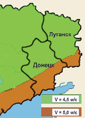
Figure 2.1 – The wind speed in the Donbass
In addition to the mean wind speed there are a number of parameters needed to determine the wind potential. These parameters include: maximum wind speed, the number of consecutive days when the wind speed exceeds 5 m/s; the duration of periods of calm or permanent wind (Fig. 2.2)
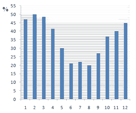
Figure 2.2 – Part of winds, suitable for wind energy needs by month (Donetsk region)
The figure 2.2 shows that the Donetsk region has the necessary wind potential for the construction of wind power plants, which is confirmed by data on the number of installed wind energy capacity in the Donetsk region – 88.3 MW (2013).
The most common wind turbines consist of a generator, liner, masts, controller, inverter and battery. The strength of the wind spins the wheel with blades, transferring torque through the gearbox to the generator shaft. In addition to direct wind turbine installation include:
- controller: converts the alternating current, which is produced by the generator to DC for charging batteries;
- batteries: are used for power storage and subsequent use in the energy system windless hours. They also align and stabilize the output voltage of the generator;
- anemoscope and wind direction sensor: responsible for collecting data on the speed and direction of wind installations in medium and high power;
- automatic power switch (ATS) provides automatic switching between multiple sources of power for the period of 0.5 seconds at the disappearance of the main source;
- inverter: converts the current from DC, which is accumulated in batteries to AC, which consumes most of the electrical appliances.
2.2 Technological scheme of wind turbines
There are two main classes of wind turbines (windmills):
- horizontal propeller;
- vertical axis.
Today, many countries are exploiting vertical-axis wind turbines with curved blades Darrieus rotor (United States, Canada, the Netherlands) or H-rotor (United Kingdom, Ukraine, Romania). The efficiency of vertical-axis wind turbine in principle does not depend on wind direction. Therefore, for them there is no need in the systems and mechanisms of orientation to the wind.
The maximum efficiency of horizontal propeller turbines is achieved only if sustainability collinear axis of the propeller and wind direction. At the same time the need to focus on wind requires in the construction of wind turbines special mechanisms and control systems for continuous monitoring of the wind situation.
It is believed that the most promising are the horizontal propeller turbines with adjustable blade angle of rotation around the axis for maintaining the stability of the angular speed of the rotor in the changing wind speed and direction, as well as load.
As an object of research we choose horizontal propeller turbines with an adjustable angle of rotation of the rotor blades.
The circuit device of modern horizontal propeller turbines with an adjustable angle of rotation of the rotor blade shown in Fig. 2.3.
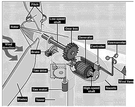
Figure 2.3 – Technological scheme of wind turbine
2.3 The wind power station as a control object
The amount of energy produced by the wind depends on:
1 Density of air.
The density depends on the number of molecules per unit volume. At normal atmospheric pressure and at a temperature of 15°С air density is 1,225 kg/m3. However, with an increase in humidity the air density decreases slightly. Due to the fact that the air in winter denser wind turbine will produce more power in winter than in summer, when the same wind speed. On the territory, situated high above sea level, for example, in the mountains, atmospheric pressure is lower and, therefore, less than the density of air.
2 The area covered by the wind turbine blades during rotation.
The larger the area of the rotor, the more power it can develop. However, the process of increasing the area of the rotor can not be reduced to a simple lengthening of the wind turbine blades. Increasing the size of the area covered by the blades during rotation, increases the load on the system at the same wind speed. To ensure that the system has withstood all load all of its mechanical components need to be strengthened. It becomes clear that such a solution requires additional financial expenses.
3 Wind speed.
The wind speed is the most important factor affecting the amount of power that the wind turbine can be converted into electricity. Most of the wind speed increases the amount of passing air masses. Therefore, with increasing wind speed increases and the amount of electricity produced by wind turbines.
Thus, in terms of input-output, the study object of regulation of horizontal propeller turbines with rotating blades can be represented as a series connection of the respective blocks: control stage – the unit of rotary blades, block production of the total torque – rotor wind turbine and electric generator unit (scheme shown in Fig. 3.1).
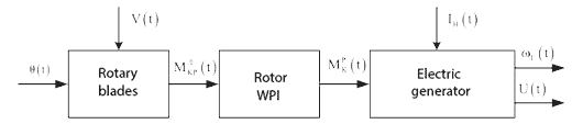
Figure 2.4 – Diagram of material flow control object
Fig. 2.4 the following notation:
- V(t) – wind speed;
- θ(t) – angle of rotation of the blades relative to the axis;
- Мtor(t) – torque generated by the blade;
- Mttor(t) – total torque generated by the wind turbine rotor;
- ωг(t) – angular rotational speed of the electric generator;
- Ir(t) – current electric load;
- U(t) – voltage generator output.
3 Development of the functional schemes of automatic control system
Functional scheme is the main technical document defining the functional-block structure of individual units of the automatic control, the control and regulation of technological process of producing electricity using appliances and equipment of windgenerator object management and automation tools.
Functional scheme is developed taking into account the composition and structure of the control system functional units selected at the stage of the design task (Fig. 3.1).
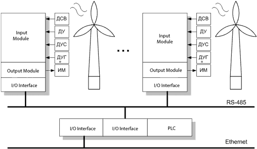
Fugire 3.1 – Functional diagram of automatic turbine control system
4. Choosing hardware control system
The criterion for the choice of hardware system is the quality, reliability, cost of equipment, the completeness and adequacy of the software, as well as the possibility of obtaining technical advice and training by highly qualified specialists of the company supplier and, of course, after-sales service.
4.1 Angle sensor and the rotation speed of the blades
Applicable T20WN sensor for measuring static and dynamic forces and torques or speeds of rotation angle (Fig. 4.1).
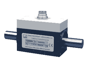
Figure 4.1 – Appearance T20WN sensor connection diagram
4.2 The gauge of angular speed of the generator
Use the torque sensor T40FM, designed to measure static and dynamic torque and force rotation or angle of rotation speeds over a wide load range.
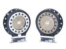
Figure 4.2 – Appearance T40FM sensor and wiring diagrams
4.3 Sensor wind speed and direction
The gauge of speed and wind direction DV-160 is designed to measure wind speed and direction. The sensor has a low inertia and high sensitivity.
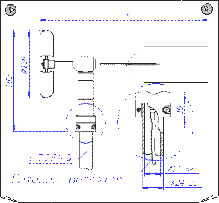
Figure 4.3 – Overall dimensions of the wind speed sensor ET-160
4.4 I/O modules
To connect T40FM sensor to the control system applicable remote pulse counter module I-7080 (measuring electric generator rotation speed) and analog input module of the remote I-7017 (torque measurement) of the company ICP DAS.
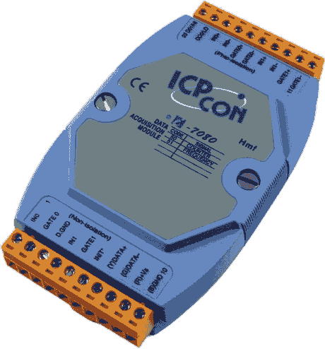
Figure 4.4 – The appearance of module I-7080
4.5 Power Supply
For supply of selected technical means of stable voltage supply applies OWEN BP14 unit.
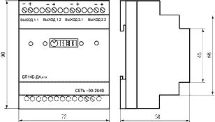
Figure 4.5 – Overall dimensions and wiring diagram PSU BP14 OWEN
Multi-channel power supply OWEN BP14B-D4.4-24 – power supply unit with an output power of 14 W with an input voltage range of 90...264 V AC, 47-63 Hz, in the housing designed for mounting on a DIN rail, 24 V supply voltage in the stable DC 4 channels. The maximum load current of 145 mA per channel.
4.6 Programmable Logic Controller
As an industrial controller using the iPAC-8000 – is a family of programmable automation controllers from the company ICP DAS. This controller combines the openness and functionality of the computer (PC) and the reliability of a programmable logic controller PLC. Controller iPAC-8000 is versatile and can be used in industrial automation, building automation, petrochemical industry, in the monitoring and remote control tasks, M2M solutions and others.
iPAC-8000 is running Mini OS7 operating system has an Ethernet port, RS-232/RS-485 and expansion slots.
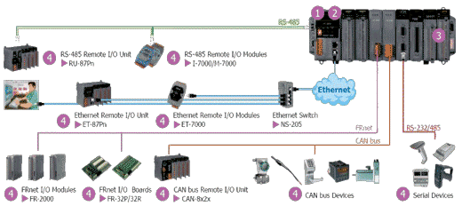
Figure 4.6 – The main components of the system PAC8000
From the family of PAC-8000 controller, select IP 8817 PC (Figure 4.6) – Compatible 80MHz Industrial Controller, 512kb the Flash, 512kb SRAM, 2xRS232, 1xRS485, 1xRS232/485, 7-Segment Display, Mini OS7, 8 expansion slots, ISaGRAF.
5 Simulation and synthesis of the work of regulators for wind turbines
5.1 Modeling the system works
We will simulate the operation of the system, setting the input impulsively variable wind. The graph shows the wind speed on animation (1 frame).
As the regulator set the proportional element with a gain KR = 1. Thus, we see the impact of feedback and additional channels. The system of setting angle of the blades depending on the wind velocity of the exhaust as follows (frame 2).
New installation angle does not exceed 3 seconds, which is quite acceptable for this channel regulation. Additional management measures for speeding up this channel is not required. But the main output signal – the angular velocity of wind turbine generator ω(t) greatly varies depending on the wind speed. The graph shows the rate of change in the frame 3.
This is completely unacceptable, therefore, need a regulator synthesis, which will provide a constant speed when the wind changes.
Animation – Dependence diagrams (animation consist of 5 frames with delay in 5 sec, number of repetition cycles – 7)
5.2 Synthesis of the regulator
5.2.1 Proportional control
First, carry out the synthesis of a proportional controller and execute quality management evaluation, instead of Gain Block Set Block PID Controller
, switch it on P
mode and using the utility PID Tune
spend call setup system. Establish the response time of the system at the level of Tresponse = 0.5 s. This gain was as follows:
KP = 6732
The simulation results are presented in animation (frame 4).
The simulation results show that when the wind speed changes of the system error. Regarding the set value output error does not exceed 5°, the transition process with the various changes in the wind speed is sufficiently small (up to 2) and meets the technical requirements for systems of this type.
Thus, we can assume that the proportional controller is quite suitable for implementation in the wind turbine control system. Get rid of the error can be fixed by increasing the order of the system and the introduction of a proportional-integrating regulator.
5.2.2 Proportional integrating regulator
In the block PID Controller
switch from P
mode to the PI
in the form of Parallel
and with the utility PID Tune
will conduct response system configuration. Establish the response time of the system at the level of Tresponse = 5 s. In this case the regulator factors:
KP PI = 4828
KI PI = 2200
The simulation results are shown in the frame 5.
The simulation results show that a system error is set equal to 0 rad/s, the transient changes in various wind speed is sufficiently small (up to 4), control error in the wind changes by nearly 50% (tmod = 10 s) reaches 20%, but it is permissible for such abrupt changes of wind speed.
МIt can be concluded that the designed controller meets the technical requirements for systems of this type.
Conclusions
The objective is – to increase in wind turbine capacity, by improving the steering angle control system windmill blades when changing wind speed and direction. To achieve this goal the following tasks:
- an analysis of the wind power plant as the object of control, input, output channels and disturbing;
- to develop a functional and structural management schemes wind energy plant, which includes channels disturbances;
- to make the choice of technical equipment and develop the concept of the automatic control system;
- to develop an algorithm of automatic control systems.
Thus, all the set objectives of the study is completed and it can be assumed that the goal of the project is achieved.
In writing this essay master's work is not yet complete. Final completion: May 2016. The full text of work and materials on the topic can be obtained from the author or his manager after that date.
List of references
- Ветроэнергетика / под редакцией Д. де Рензо: Пер. с англ. Я. И. Шефтера. – М.: Энергоатомиздат, 1982. – C. 272.
- Дорф Р., Бишоп Р. Современные системы управления: Пер. с англ. Б. И. Копылова. – М.: Лаборатория Базовых Знаний, 2004. – C. 832.
- Клюев А. С. Проектирование систем автоматизации технологических процессов / А. С. Клюев, Б. В. Глазов, А. Х. Дубровский. – М.: Энергия, 1980. – C. 345.
- Куликовский Н. Н. Система управления электроустановкой / Н. Н. Куликовский // ПиКАД. – 2003. – №1-2. – С. 20-21.
- Кривцов В. С. Неисчерпаемая энергия. Кн.1. Ветроэнергогенераторы: учебник / B. C. Кривцов, A. M. Олейников, А. И. Яковлев. – X.: Нац. аэрокосм, ун-т
Харьк. авиац. ин-т
, Севастополь: Севаст. нац. полит. ун-т, 2003. – C. 400. - Сабинин Г. Х. Характеристики ветродвигателя в зависимости от направления ветра. Труды ЦАГИ, вып. 28 /Г .Х. Сабинин. – М.: ЦАГИ, 1926. – C. 112.
- Солод М. Ветроэнергетика. Попытка реанимации? / М. Солод //Наука и техника. – 2008. – С. 21-26.