
Abstract
Content
- Introduction
- 1. Theme urgency
- 2. Goal and tasks of the research
- 3. Invacare Storm XS powerchair characteristics
- 4. Hardware development
- 5. Software development
- References
Introduction
Among products intended for people with disabilities, those compensating violations of the musculoskeletal system of man, are allocated to a special class, for example, canes, crutches, lower limb prostheses and wheelchairs. Wheelchairs could be driven by the user or by accompanying person. Wheelchairs can have a mechanical drive, in when the wheels are driven by the power of the hands, or an electric drive, which includes: battery, power converter, microcontroller, input device and reducer.
Such wheelchairs are designed for movement not only indoors, but also on the street, so it is important that a convenient and reliable control system is programmed in the microcontroller, also considering the absence of a speed sensor.
1. Theme urgency
The problem of helping people with disabilities is one of the most difficult, requiring not only the understanding of society, but also the participation of many specialized agencies and structures in this process. The rehabilitation of disabled people is not only the treatment and improvement of the state of health, but also the process of achieving maximum independence in society. The most suitable devices for this are limb prostheses and powerchairs.
2. Goal and tasks of the research
The goal of the master's work is to study the existing powerchairs and the development of the electric drive control system for the Invacare Storm XS powerchair.
To achieve this goal, it is necessary to solve the following tasks:
- To study the existing systems of electric drives on modern powerchairs;
- To select the hardware components of the system (controller, power converter, sensors, input device);
- To develop a mathematical model of the powerchair speed control system;
- To develop an executable program for the controller;
- To check the functionality of the implemented system.
Planned results:
- A mathematical model of the powerchair speed control system;
- A working electric drive system implemented into the Invacare Storm XS powerchair.
3. Invacare Storm XS powerchair characteristics
Invacare Storm XS powerchair (Fig. 1) is one of the first models of the series. This is a combined type powerchair (suitable for both indoor and outdoor use) with individual rear wheels drive.

As drive motors, the GP8040SB-SRG1 direct-current brushed motors with a rated voltage of 24 V, rated current of 14 A and rated speed of 4000 rpm are used. The gear ratio is 25.1, and the diameter of the drive wheels is 36 cm. The system has two batteries with a rated voltage of 12 V each and a capacity of 40 Ah. This wheelchair is convenient because the armrests and the footrest are adjusted in height, and also there is an amortization system of the rear wheels. Electromagnetic brakes with a nominal force of 2.2 Nm are attached to the motors. The weight of the wheelchair is about 70 kg without batteries and 103 kg with batteries. The rated carrying capacity is 110 kg.
Hardware development
To implement the control system of the powerchair, it is necessary to supplement the system with missing elements: a microcontroller, an input device and a power unit (driver for the H-bridge). Also, to ensure good control quality, it is necessary to supplement the system with current and speed sensors for their regulation. Current control will ensure high-quality transients and current limiting, which will result in a lower battery discharge rate. Speed control will ensure the synchronization of the wheels speeds with uneven load on them and smooth start and braking of the wheelchair.
Arduino Uno R3 was chosen as the microcontroller for the system (Fig. 2). It includes: 14 digital inputs/outputs (6 of them can be used as PWM outputs), 6 analog inputs, a 16 MHz crystal oscillator, a USB connector, a power connector and a reset button. To start the device, it's enough to simply supply power from the AC/DC adapter or battery, or connect it to the computer via an USB cable. The clock frequency of 16 MHz is enough for the computational operations of the working algorithm, and the number of inputs/outputs is sufficient to connect all the necessary peripheral devices, which together with the low cost of the board makes this microcontroller a good choice for the master’s work.

As the input device a two-axis joystick KY-023 was chosen, which has two 5 V analog outputs (one per axis) and one digital output for the clock button. This joystick is easy to connect and easy to use.
As the power converter, the Monster Moto Sheild VNH2SP30 board was selected (Fig. 3), where VNH2SP30 is the name of the bridge driver for high-power DC brushed motors. This driver is designed for motors with rated voltage of up to 41 V, and current up to 30 A. It uses MOSFETs keys manufactured by STMicroelectronics and supports PWM control with frequency up to 20 kHz. A feature of such driver is an integrated current sensor, which outputs a current signal proportional to the motor current. The board itself is specially designed for Arduino Uno, which greatly simplifies its use in this case.

It was planned to use the built-in current sensors of the drivers, however, due to the production defect, only one driver has a working current sensor, so an external current sensors ACS758 was chosen. The selected model LCB-050B is a bipolar sensor, can measure up to 50 A and has an output voltage signal of 40 mV/A. Since the sensor is bipolar, it should be noted that the output signal at zero current will be half the supply voltage and the count will start from this value. This sensor was chosen because it is easy to use, it is bipolar and covers all the necessary range of currents.
The two-loop speed control system cannot be created without measuring the engine speed, however, there is no possibility of connecting the speed sensor, therefore, it was decided to use an indirect speed measurement via the motor's EMF. This method does not require a large number of connections, has a simple algorithm, but imposes some restrictions on the system. Since EMF measurement is only possible with closed upper-arm transistors, the PWM opening angle cannot be equal to 100% to allow the measuring of the EMF. This will somewhat reduce the maximum motor speed (about 2%), but the method will give the necessary accuracy of calculating the motor speed in case if a sufficient PWM frequency is set.
Software development
As an electric drive control system, a two-loop speed control system with feedback via the motor EMF was chosen. The use of a current loop will allow the system to limit the amplitude of the current, which will secure the elements of the board, and will also reduce the discharge rate of the batteries. The speed loop will allow the user to easily control the movement of the wheelchair, ensure the smoothness of the starting and braking modes, and also eliminates the need for synchronization of wheel speeds, which would be one of the most important conditions for an open-loop system. The functional diagram of the system is shown in Figure 4. The following blocks are represented on it: RG – ramp-function generator; EC – the proportional-integral-differential controller of the EMF; CC – proportional-integral current controller; AB – accumulator battery; CS – current sensor; TS – tension sensor; SC – speed calculator.
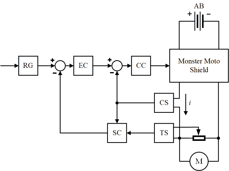
The ramp-function generator receives a speed reference signal from the input device, in this case it is a two-axis joystick. The ramp-function generator is required to provide smooth starting and braking drive modes. The calculated speed signal is subtracted from the ramp-function signal. The process of calculating the speed through EMF is described below. The error signal is an input to the PID controller of the EMF, which outputs the current reference signal. The difference between the current reference signal and the current sensor signal is an input to the PI current controller. The output of the current controller is the PWM control signal, which goes to the Monster Moto Shield power converter.
The process of calculating the speed through the EMF of the motor comes out of the equations (1) and (2).
 |
(1) | |
 |
(2) |
where U is the supply voltage, V; E is the motor EMF, V; Ia – motor armature current, A; RΣ – total armature resistance, Ohm; C – design constant of the motor; ω – angular rotation speed of the motor, rad-1.
To calculate the design constant of the motor, it is needed to calculate the rated motor EMF first. When the rotor of the motor rotates, the EMF induced in the coil operates against the supply voltage. It is also necessary to take into account the voltage drop in the coil. Thus, the nominal EMF can be calculated from the equation (3).
 |
(3) |
After this, it is possible to calculate the design constant of the motor, using equation (2). Then, knowing the design constant, it is possible to calculate the motor speed by measuring the EMF by measuring the voltage from the motor terminals when the driver's upper-arm keys are closed, then subtracting the voltage drop in the winding and multiplying the obtained value by the design constant. The peculiarity of this method is that it is necessary to measure the voltage from the terminals for determining the motor EMF only when it is not energized, that is, when the semiconductor switches of the upper arms of the H-bridge are in the closed state. This somewhat complicates the control algorithm since it is needed to synchronize the work of the microcontroller ADC with the frequency of the PWM signal applied to the transistors. Also, such approach to speed control imposes some limitations on the PWM signal:
- The PWM opening angle cannot be 100% to allow the measurement of the motor EMF;
- The PWM frequency must be at least 2 kHz in order to ensure sufficient accuracy of the speed calculation.
It is also necessary to take into account that the measured EMF of the motor is a voltage signal and after the passage of the voltage divider there will be a significant noise in this signal. To get rid of noise, thereby improving the quality of regulation, it is necessary to install an RC-chain parallel to the measured voltage. It will work as a low-pass filter. It is recommended to adjust the cutoff frequency at 700-1000 Hz for this case, choosing the resistance and capacitance values accordingly. To increase the accuracy of the speed calculation, it is recommended to use the average value of the calculated speed over several PWM periods. This is important in case of using PID speed controllers.
References
- Electric Wheelchairs: Types & Reviews of Powerchairs. Режим доступа:
Disabled World
- Инвалидная коляска. Материал из Википедии – свободной энциклопедии. Режим доступа:
ru.wikipedia.org
- Инвалидные коляски и пути их совершенствования. Режим доступа:
www.metodolog.ru
- Оффициальный дистрибьютор Invacare в Украине. Режим доступа:
invacare.kiev.ua
- Permobil General Product Info. Режим доступа:
www.permobil.com
- Официальный дилер завода по разработке и сборке американских мобильных скутеров Pride Mobility для малоподвижных людей в России. Режим доступа:
mobilityscooter.ru
- Компания
Мега-Оптим
– технические средства реабилитации. Режим доступа:www.mega-optim.ru
- Компания
Ортоника
– технические средства реабилитации. Режим доступа:store.ortonica.ru
- Микроконтроллер Arduino Uno, общие сведения. Режим доступа:
arduino.ua
- Ипанов Дмитрий Александрович –
Компенсация и облегчение воздействия сопровождающего лица при управлении инвалидным креслом с электроприводом
– Реферат по теме магистерской работы. Режим доступа:masters.donntu.ru
- VNH2SP30-E Driver Data Sheet. Режим доступа:
www.pololu.com
- ACS758xCB Current Sensor Data Sheet. Режим доступа:
www.allegromicro.com
- AB-021: Measuring RPM From Back EMF. Режим доступа:
www.precisionmicrodrives.com
- Сайт компании UNA Wheel. Режим доступа:
unawheel.ru
- Усольцев А.А. Общая электротехника: Учебное пособие. – СПб: СПбГУ ИТМО, 2009. – 301 с.
- Анучин А.С. Системы управления электроприводов: учебник для вузов. – М.: Издательский дом МЭИ, 2015. – 373 с.