Abstract
Content
- Introduction
- 1. Theme urgency
- 2. The purpose and objectives of the study, the planned results
- 3. Practical section
- Conclusion
- References
Introduction
Elements with three incompatible states: healthy, a failure type open circuit
and a failure type short circuit
can be distinguished in the systems: power supply, gas supply, water supply, etc. Analogs of elements with three incompatible states in such systems can be protective switching devices, taps, valves of various types, stop valves, plugs and other types of flow interrupters (electric power, gas, liquid, information, etc.), for which are inoperable the flow is not interrupted (short circuit
) or is not transmitted (open circuit
) [3].
In those cases, if it is necessary to increase the reliability of the designed system without changing the reliability of its component parts, it is usual to introduce redundant (backup) elements or change the block diagram of the network. For systems consisting of elements that can be in three incompatible states, the introduction of redundant elements with three states can not only not increase its reliability, but even reduce it. Everything will depend on the ratio between the different types of failure of the circuit element, its configuration and the number of backup elements or their groups.
1. Theme urgency
The development of new and improved existing methods for assessing the reliability of nonrecoverable systems, whose elements may be in three incompatible states, is an important scientific problem, the solution of which will significantly improve the accuracy of prediction of their reliability, both at the design stage and at the stage of reconstruction and operation.
2. The purpose and objectives of the study, the planned results
The purpose of the master's work is to review one of the existing methods for assessing the reliability of unrecoverable, complex in structure systems, elements of which can be in three incompatible states – the Minimum Sections
method.
The main objectives of the study:
- A review of the literature and the definition of existing methods for assessing the reliability of unrecoverable, complex in structure systems, whose elements may be in three incompatible states.
- Parsing the
Minimum Sections
method. - The application of this method of calculation on a specific example.
Planned results:
- Determination of the accuracy of the calculation of the reliability of unrecoverable structurally complex schemes for t ≤ 0.1 year, the proposed method using schemes
minimum sections
. - Comparison of calculation accuracy with other known methods for calculating the assessment of the reliability of nonrecoverable systems, whose elements may be in three incompatible states.
3. Practical section
The equivalent circuit of a complex system, to assess its reliability is shown in Fig. one:

Figure 1 – System replacement scheme
(animation: 8 frames, 3 reiteration cycles, 75 kilobytes)
For the equivalent circuit elements (Fig. 1), the following failure rates are set: λo1 = 0,58 year−1; λs1 = 0,34 year−1; λo2 = 0,42 year−1; λs2 = 0,25 year−1; λo3 = 0,75 year−1; λs3 = 0,25 year−1; λo4 = 0,5 year−1; λs4 = 0,34 year−1; λo5 = 0,75 year−1; λs5 = 0,25 year−1; λo6 = 0,34 year−1; λs6 = 0,25 year−1; λo7 = 0,67 year−1; λs7 = 0,5 year−1; λo8 = 0,5 year−1; λs8 = 0,42 year−1.
Determine the lower estimate Rн of the fact that during the time t = 0.1 year there will be no disconnection or pass-through emergency current between the nodes input
and output
of the equivalent circuit.
Using formulas (2) and (3), the initial data of the example, for t = 0.1 year we find qoi, qsi (i = (1÷8)): qo1 = 0,0554; qs1 = 0,0325; qo2 = 0,0406; qs2 = 0,0242; qo3 = 0,0714; qs3 = 0,0238; qo4 = 0,0479; qs4 = 0,0326; qo5 = 0,0714; qs5 = 0,0238; qo6 = 0,033; qs6 = 0,0243; qo7 = 0,0632; qs7 = 0,0472; qo8 = 0,0478; qs8 = 0,0401.
To obtain the minimum section
scheme (the failures of elements of the open circuit
type are taken into account), we use the scheme in Fig. 1 and table is filled. 1 in accordance with the algorithm described above.
Table 1 – Algorithm for obtaining minimum sections
when accounting for failures of a open circuit
type
| № | Substitution pattern node | Elements of communication between nodes | Section |
Minimum section |
| 1 | 2 | 3 | 4 | |
| 1 | Ао | 1,2,3 | 1.2.3 | 1.2.3 |
| 2 | Ао+А1 | 1, |
1.3.4.7 | 1.3.4.7 |
| 3 | Ао+А2 | 1,2, |
1.2.6.7.8 | 1.2.6.7.8 |
| 4 | Ао+А3 | 2.3.4.5.6 | 2.3.4.5.6 | |
| 5 | АоА1+А3 | 3.5.6.7 | 3.5.6.7 | |
| 6 | АоА1+А2 | 1, |
1.4.6.8 | 1.4.6.8 |
| 7 | АоА2+А3 | 2.4.5.7.8 | — | |
| 8 | АоА1А3+А2 | 3,5,6,7 3,6,7,8 |
5.8 | 5.8 |
Section 7 (2.4.5.7.8) is not minimal, since it already includes the minimum section
(5.8), therefore column 4 in this case remains empty.
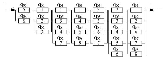
Using the resulting fourth column (Table 1), we construct the minimum cross section
scheme, arranging their cross sections as follows:

Figure 2 – The scheme of minimum cross sections
with regard to failures of elements open circuit
To obtain the minimum cross-section
scheme (the refusal in the triggering
element is taken into account), you should use the diagram in fig. 1 and fill in the table. 2 in accordance with the rule described above.
Table 2 – Algorithm for obtaining minimum sections
when taking into account element failures in triggering
| № | Circuit nodes through which emergency current flows | Elements of communication between nodes | Section |
Minimum section |
| 1 | 2 | 3 | 4 | |
| 1 | Ао; А2; А4 | 3,7 | 3.7 | 3.7 |
| 2 | Ао; А3; А4 | 1,6 | 1.6 | 1.6 |
| 3 | Ао; А3; А2; А4 | 1,6,8 | 1.6.8 | 1.6.8 |
| 4 | Ао; А1; А3; А4 | 2,4,5 | 2.4.5 | 2.4.5 |
| 5 | Ао; А1; А2; А4 | 2,7,8 | 2.7.8 | 2.7.8 |
| 6 | Ао; А2; А3; А4 | 3,6,5 | 3.6.5 | 3.6.5 |
| 7 | Ао; А1; А3; А2; А4 | 2,4,6,8 | 2.4.6.8 | 2.4.6.8 |
| 8 | Ао; А2; А1; А3; А4 | 3,7,4,5 | 3.7.4.5 | 3.7.4.5 |
| 9 | Ао; А3; А1; А2; А4 | 1,4,7,8 | 1.4.7.8 | 1.4.7.8 |
| 10 | Ао; А1; А2; А3; А4 | 2,7,6,5 | 2.7.6.5 | 2.7.6.5 |
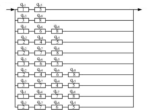
Using the data table. 2, column 4, we construct the scheme minimum sections
(the failures in the triggering
of its elements are taken into account):

Figure 3 – The scheme of minimum cross sections
when accounting for failures in triggering
elements
Using substitution schemes for minimum sections
, fig. (2 and 3), formulas (6), (8), (7), (9) we find:
Substitute the values qoi(0,1), qsi(0,1), (i = (1÷8)) in the resulting formulas, we find:
Using the formula (10) we find:
A similar result was obtained when solving the same problem using the triangle–star
and star–triangle
method [9], i.e  = 0,9946. A similar result was obtained if the problem was solved by exact methods based on the use of the notion of the algebra of tuples [10] and using the logical-probabilistic method [7], that is, in these cases: R = 0,9946.
Conclusion
- One of the possible ways to assess the reliability of structurally complex non-recoverable systems, whose elements may be in three incompatible states, is proposed.
- Unless the reliability of non-recoverable systems is taken into account, failures in the
actuation
of the protective switching devices, i.e. Qsн = 0, then, for this particular example, the reliability of the system is overestimated by 2 times. - Accuracy of calculations of reliability of non-recoverable structurally complex schemes for t ≤ 0.1 year, the proposed method using schemes
minimum sections
does not differ from the known. - The proposed method for assessing the reliability of complex nonrecoverable systems, whose elements may be in three incompatible states, is based on simple and understandable to the engineer concepts and can be used to train electrical engineers of any specialties.
At the time of writing this essay, the master's work is not yet completed. Estimated completion date of master's work: June 2019. The full text of the work and materials on the topic can be obtained from the author or his manager after the specified date.
References
- Беляев Ю. К. Надежность технических систем: Справочник [текст] / Ю. К. Беляев, В. А. Богатырев, В. В. Болотин и др., Под ред. И. А. Ушакова. – М.: Радио и связь. – 1985 – 608 с.
- Рябинин И. А. Надежность и безопасность структурно-сложных систем [текст] / И. А. Рябинин. – С.П.Б. Изд-во С.–Петербург. ун-та. – 2008. – 276 с.
- Ковалев А. П. О преобразовании
Звезда
–треугольник
при расчетах надежности сложных по структуре схем [текст] / А. П. Ковалев, А. В. Спиваковский // Электричество. – №10. – 1998. – с.70–74. - Эндрени Дж. Моделирование при расчетах надежности в электроэнергитических системах: [текст] / Дж. Эндрени. Пер. с англ / Под ред Ю. Н. Руденко. – М.: Энергоатомиздат. – 1983. – 336.
- Фокин Ю. А. Расчет надежности систем энергоснабжения [текст] / Ю. А. Фокин, А. М. Харченко // Электричество – №8. – 1982. – с. 5–10.
- Белоусенко И. В. О расчете надежности систем электроснабжения газовых промыслов [текст] / И. В. Белоусенко, М. С. Ершов, А. П. Ковалев, В. В. Якимишина, О. А. Шевченко // Электричество. – №3. – 2004. с. 23–28.
- Ковалев А. П. Применение логико-вероятностных методов для оценки надежности структурно-сложных систем [текст] / А. П. Ковалев, А. В. Спиваковский // Электричество. – 2000. – №9. – с. 66–70.
- Диллон Б. Инженерные методы обеспечения надежности систем [текст] / Б. Диллон, Ч. Сингх. Пер. с англ. – М.: Мир. – 1984. – 318 с.
- Ковалев А. П. Расчет надежности невосстанавливаемых систем, элементы которых могут находиться в трех несовместных состояниях [текст] / А. П. Ковалев, И. И. Москвина, Т. Г. Бусыгин // Промышленная энергетика. – 2018. – №3. – с. 7–13
- Кулик Б. А. Логико-вероятностные методы на алгебре кортежей. – В сб.: Теория информационная техника моделирование безопасности сложных систем – С.П.Б.: ИПМ РАН. 1995. Вып.5, Препринт 123, с. 18–43.
