
Abstract
Content
- Introduction
- 1. Theme urgency
- 2. Goal and tasks of the research
- 3. Modeling of precipitation and acceleration processes of wheel billets on presses with a force of 20 MN, 50 MN and 100 MN
- 3.1 Modeling of the process of stamping wheel blanks on a sedimentary press of 20 MN
- 3.2 Modeling of centering and distillation of blanks on a billet press with a force of 50 MN
- 3.3 Modeling of a billet molding operation on a forming press with a force of 100 MN
- Conclusion
- References
Introduction
This work is devoted to the design of the calibration rolls and dies in the production of solid-rolled railway wheels. Designing is the process of creating a project for the manufacture of a metal deformation tool throughout the press-rolling line of the wheel-rolling shop. During the design process, drawings and technical calculations are performed. [1].
The task of designing a finishing wheel profile includes drawing, as well as calculating the mass of the wheel and a number of parameters of its radial section profile. It arises as one of the stages when creating a new wheel design. After designing the profile of the wheel, the stress-strain state of its elements is evaluated from the application of mechanical and thermal operating loads by finite element modeling. In the case of unsatisfactory results, the design is changed, and then the design of the advanced wheel profile and the specified verification calculations are performed.
Secondly, the task of designing a profile of a finishing wheel arises at the factory at the stage of coordinating with the customer its mass in the case when the finished machined wheels are shipped, and at the stage of designing the profile of a rough wheel. Information about the profile of the finishing wheel is also necessary for the implementation of its machining on programmable machines.
1. Theme urgency
Relevant to the modern theory of wheel rolling production is the creation of methods for designing technology for deforming accurate by weight (the difference between blanks by weight to 1%) wheel blanks, which would ensure high accuracy of prediction of forming metal and power parameters of the processes of forming and rolling blanks. The solution of this problem requires a change in the formulation of the relevant boundary-value problems and methods for their implementation in accordance with the technical and technological features of the production of wheels on a particular press-rolling line.
2. Goal and tasks of the research
The aim of the work is to improve the technology of punching railway wheels with a flat-disk in the conditions of JSC "VMZ" Ø 957mm. In the present work, the problem of simulating a multi-transition process of deforming wheel blanks with its subsequent implementation in the DEFORM 3D system is set. The simulation was performed for a non-stationary thermal regime of the workpiece, that is, taking into account the heat exchange processes of the metal being processed with the environment, both during deformation and during interdeformational pauses, as well as taking into account the thermal effect of plastic deformation.
3. Modeling of precipitation and acceleration processes of wheel billets on presses with a force of 20 MN, 50 MN and 100 MN
3.1 Modeling of the process of stamping wheel blanks on a sedimentary press of 20 MN
A preliminary draft on a 20 MN press is made in order to reduce the height and increase the cross-sectional area of the blanks. The precipitate is used to improve the structure and mechanical properties of the metal blanks, as well as to reduce the unevenness of the properties in the axial and radial directions.
In the process of precipitation, the scale is removed from the side surfaces of the blanks, as well as the scale that remained after water jetting from the end surfaces. The press with a force of 20 MN is a hydraulic vertical four-column with an architain and a bed installed on the foundation. Between the bed and architrave located traverse, which moves through the columns of the press. A plate is installed on the base of the press and the support, along the guides of which the press table moves. The plate rests on one side of the bed frame, and on the other it is supported by two hydraulic cylinders, which are under constant pressure.
The traverse is lowered by the plunger of the working cylinder, the traverse is lifted by two lifting cylinders placed in the tides of the architrave. Sedimentary plates are attached to the traverse and the table.
The working cycle of the press consists of lowering the traverse to contact with the workpiece, the working stroke - precipitation of the workpiece and lifting the traverse to its original position. The lowering of the traverse begins after the manipulator supplies the workpiece to the press table during its return to the initial position. The set value of the draft is provided by the automatic control of the crosshead. To control the height of the upset billet, the press is equipped with a traverse indicator in the form of a dial with a rotating arrow. The thickness variation of the upset blanks should not exceed 2 mm.
Before serving the workpiece to the press table, dispensing process is applied to the middle of the lower compression plate in order to prevent the pressing of dross, which has not separated after water jetting. It is also fed to the upper end surface of the workpiece.
After precipitation, the billet is removed by the manipulator from the working area of the press with a force of 20 MN. To prevent heating and reduce wear, the crimp plates are cooled with water after removal of the workpiece. Scale from the bottom plate is also removed with
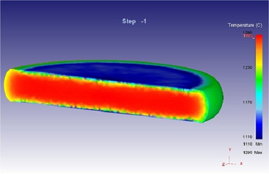
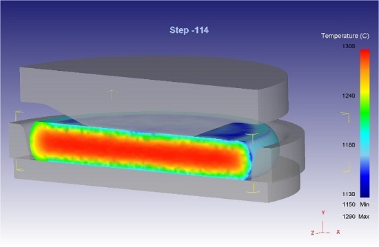
Simulation results. At the first stage of the research, the process of cooling the billet in the air during its transportation (transportation time - 25 s) was performed along the roller table from the furnace to a sedimentary press with a force of 20 MN. The temperature distribution in the workpiece after its transportation and holding (exposure time –5 s) on the bottom plate of the 20MN press is shown in Figure 3.1.1. The average temperature of the metal on the surface of the workpiece before the draft is 1260 - 1280°C. The free draft of the workpiece is produced to a height of 118–120 mm. The results of the simulation of the draft precipitation process are presented in Figure 3.1.2. The obtained precipitation strength (24.9MN) is the maximum possible for this press. It is reached at the pressure of the working fluid 31,4MN/m2 [2]
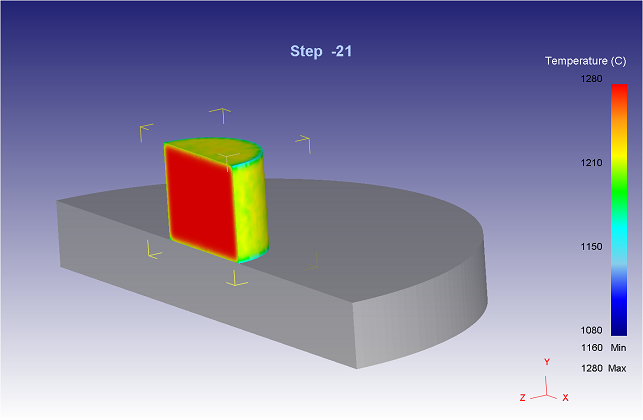
Figure 3.1.1 - Procurement after transportation and holding on the bottom plate
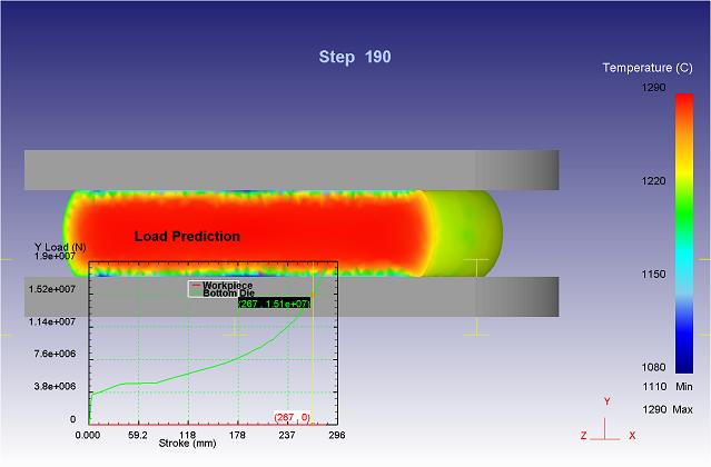
Figure 3.1.2 - Procurement after precipitation on a press with a force of 20MN
3.2 Modeling of centering and distillation of blanks on a billet press with a force of 50 MN
On the roller table, the billet is fed to a tilter installed in front of a 50 MN press and edged by 180 °. For more complete removal of the secondary scale, the end surfaces of the workpiece are cleaned with metal brushes before and after the tilter, after which the workpiece is fed to the press with a force of 50 MN.
The deformation operations on the press with a force of 50 MN are performed with the goal of a regulated distribution of metal between the peripheral and central parts of the workpiece. A press with a force of 50 MN - a hydraulic vertical four-column consists of fixed crossbeams - a bed and an architrave, interconnected by columns.
A hydraulically driven ejector is installed at the bottom of the frame. The press is equipped with a technological ring centering device consisting of a lifting mechanism with a hydraulic drive and a yoke. The bottom plate holder with its shank is installed in the bore of a square plate, moving with the help of four adjusting wedges. The lower and upper sedimentary plates are installed in plate holders.
A cone plate is installed on the press with a force of 50 MN in the upper plate holder. The billet after its preliminary precipitation on a press with a force of 20 MN is placed on a press table with a force of 50 MN and centered with a technological ring. The precipitation and distillation of the blanks are performed in one operation. Moreover, if the distillation is carried out not on the entire height of the wedge, then additional draft precipitation does not occur. The advantage of this technology is associated with the exception of the operation of the distillation of blanks by the punch and, accordingly, with the reduction of the cycle on the press of 50 MN. For its implementation, exact mass of the billet with a weight of no more than ±5 kg is required. This is due to the fact that in the process of preliminary precipitation of the original blanks on a press with a force of 20 MN, a sufficiently stable diameter is required to ensure that, as indicated above, they are centered by a technological ring of a press with a strength of 50 MN.
The set value of the draft and the distillation of the workpiece is provided by the automatic control of the crosshead. The control of the precipitation value is carried out according to the mark on the disc indicator of the traverse. In the technological ring, the workpiece should be crimped axisymmetrically to obtain a uniform imprint over the entire side surface of the workpiece. After deformation, the scale is removed from the workpiece with air, and from the tool with water during its cooling. Failure to comply with the technology and unsatisfactory setting up of the equipment, as well as the development of a deformation tool and other parts, leads to the appearance of defects on workpieces after a press with a force of 50 MN such as: pressing the scale; different thickness of blanks; the deviation from the predetermined shape of the workpiece after distillation by a cone plate; local recesses on the surface of the workpiece; flaws; folds on the end surfaces of the workpiece.
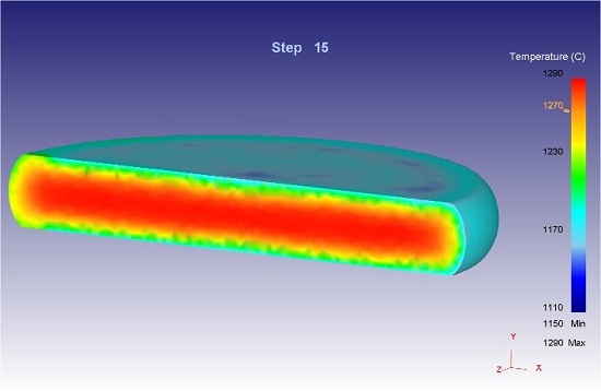
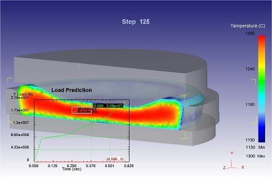
Simulation results After free precipitation, the billet is fed to the press of 50 MN (transport time - 10s) for distillation in the process ring. Before pressing 50 MN, the billet is turned 180° to equalize the temperature from the upper and lower sides of the billet. Figure 3.2.1 a, b shows the temperature distribution in the workpiece before and after transporting it to the press of 50 MN and holding the workpiece (holding time - 5s) on the bottom compression plate of the press. The average temperature of the metal on the surface of the workpiece before distillation is 1250 - 1270°C.
а)
б)
Figure 3.2.1 - Procurement before (a) and after transportation and holding on the bottom plate (b)
After laying the workpiece on the crimping plate, the technological ring is centered on the axis of the press and lowering the traverse of the press before the cone plate comes into contact with the workpiece. The results of the simulation of the process before and after the workpiece distillation on a press with a force of 50 MN are presented in fig. 3.2.2 a, b.
а)
б)
Figure 3.2.2 - Procurement before (a) and after distillation (b) on a press with a force of 50MN
3.3 Modeling of a billet molding operation on a forming press with a force of 100 MN
With a press with a force of 50 MN, the billet is transferred by a cleaning peeler onto a discharge roller table and transported to a molding press with a force of 100 MN. In this case, it is subjected to descaling with metal brushes. The deformation of the workpiece on a press with a force of 100 MN is performed in order to obtain a molded workpiece with the final dimensions of the hub and the adjacent part of the disk, as well as the preparation of the rim and the adjacent part of the disk for subsequent rolling at the wheel rolling mill.
The press with a force of 100 MN - a hydraulic vertical four-column has two fixed cross-beams - a bed and an architrave, connected by four columns. An architrave has a working cylinder of the press, as well as two lifting differential cylinders and two balancing cylinders. The plungers of these cylinders are mounted on a movable cross member. The cross-plate plate, in which the upper ejector of the workpiece is mounted, is attached to the traverse. The ejector cylinder works in conjunction with lifting traverse cylinders. The technological cycle of operation of a press with a force of 100 MN includes the following operations: laying the workpiece on the lower forming die; centering the workpiece on the stamp; lowering the traverse to the contact of the upper stamp with the workpiece; working stroke - forming billet; lifting traverse to its original position; removing the molded workpiece with ejector from the upper and lower punch and issuing it on the roller table.
The amount of deformation of the workpiece on the press is provided by the automatic control system of the cross head of the press. The specified value of the disk thickness is controlled by the mark on the traverse disc path indicator. There should also be a clear design of the end surfaces of the hub and a uniform imprint of the forming ring around the entire circumference of the outer surface of the rim. Failure to comply with the technology and unsatisfactory setting of the presses, as well as the development of dies and other parts leads to the appearance of defects on the wheel blanks after a press of 100 MN such as: razrashirinnost and thickness of the rim; disc thickness; thick or thin disc at the hub; hub crease; hub displacement, non-fulfillment or differential; imprints on the surface of the wheel blanks. After lifting the yoke, the molded workpiece is removed from the upper and lower dies by ejectors and held in a raised position until the workpiece is grasped by the putter.
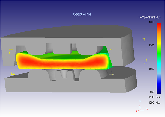
Simulation results After the distillation operation, the billet is fed (transport time - 20s) to the molding press with a force of 100 MN. Figure 3.3.1 (a) shows the temperature distribution in the workpiece after it has been transported to the 100 MN press and held at the lower die (exposure time is 8.5s). The average temperature of the metal on the surface of the workpiece before forming in the dies is 1130 - 1160°C. The results of modeling the process of forming a blank on a press with a force of 100 MN are presented in Figure 3.3.1 (b).
а)
б)
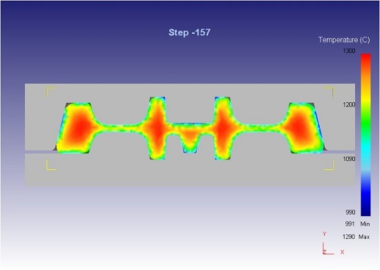
Figure 3.3.1 - Procurement after transportation, holding on the lower die (a) and molding on a press with a force of 100MN (b)
The low value of the forming force is explained by the fact that during modeling the amount of billet distillation on a press of 50 MN provided, on the one hand, the hub (see Figure 3.3.1 (b)), and on the other hand, the elimination of metal from the central cavity of the molding dies to the peripheral one. Naturally, in practice, it is not possible to precisely pick up the amount of distillation, including due to the weight of the blanks. Therefore, in real conditions of industrial production, the forming force, taking into account losses, can reach 90 MN due to premature filling of the central cavity of the dies in the hub area and changing the direction of metal flow in the disk area to one-sided. Due to this, avoid getting an unrecoverable type of marriage, "non-fulfillment of the hub", with the strength of punching at the press.
From figure 3.3.1 (b) it is clear that the peripheral cavity of the dies, which forms the upper end of the rim for rolling, is not completely and unevenly filled with metal. Such a picture of metal forming is in good agreement, not only qualitatively, but also quantitatively, with experimentally established patterns of metal forming in forming dies by the authors of [3],[4],[5]
Conclusion
Thus, the formulation and implementation of the task of finite element modeling of the processes of slump, distillation and molding of wheel blanks in relation to the conditions of press-rolling lines of PJSC "VSW" was carried out. The 3D simulation results obtained in the DEFORM system as a whole correctly reflect the main regularities of the analyzed processes established in the conditions of industrial wheel production. The mathematical models developed and implemented in DEFORM 3D were also used to evaluate the effectiveness of new technological modes and methods of deformation, as well as creating analytical dependencies for the rapid calculation of the parameters of metal forming and forces during stamping and rolling of wheel blanks.
On a press with a force of 50 mn sediment and the disintegration of the workpiece is carried out simultaneously in one move the traverse of the press. But pre-centering the technological ring with the filed table. For the implementation of this process, exact mass of the billet with a weight of ±5 kg is necessary. This is due to the fact that in the process of preliminary precipitation of the original blanks on a press with a force of 20 MN, a sufficiently stable diameter is required to ensure that they are centered by a technological ring of a press of 50 MN.
Using the experimental data on the power parameters of the rolling process as initial information, the assessment of the adequacy of the simulation results was performed by comparing the calculated parameters of the shape change of the workpiece with similar parameters recorded in industrial conditions. The values of the forming forces, the temperatures of the workpieces and the parameters of their shaping were obtained in the simulation are in good agreement with the experimental data obtained in the conditions of industrial production of wheels Ø 957 mm.
References
- Яковченко, А.В. Проектирование профилей и калибровок железно-дорожных колес : монография / А.В. Яковченко, Н.И. Ивлева, Р.А. Голышков. - Донецк: ДонНТУ, 2008. – 491с.
- Гун Г.Я. Теоретические основы обработки металлов давленим / Г.Я. Гун. – М.: Металлургия, 1980. – 456 с.: ил.
- Прогнозирование и способ устранения образования зажимов при формовке колесных заготовок / Б.Г. Каплунов, В.Н. Крашевич, М.И. Староселецкий, А.В. Белущенко // Изв. вузов Черная металлур-гия. – 1991. – № 1. – С. 55–56.
- Шифрин М.Ю. Резервы производительности и выхода годного при прокатке колес / М.Ю. Шифрин. – М.: Металлургия, 1989. – 144 с.: ил.
- Шифрин М.Ю. Рациональный режим осадки обода колесной заго-товки / М.Ю. Шифрин // Сталь. – 1993. – № 5. – С. 52–54.