
Abstract
Content
- Introduction
- 1. Organization and structure of repair production at ferrous metallurgy enterprises
- 2. Technology and designs of plasma cutting machines
- 2.1 Brief description of the plasma cutting process
- 2.2 The general structure and principle of operation of the plasma cutter
- 2.3 Overview of plasma cutting devices
- 3. Description of the design of the model of a portable cnc plasma cutting machine
- 4. Program setting of the plasma cutter
- Conclusions
- List of sources
Introduction
An integral component of the reliability of the equipment is maintainability, the indicators of which (duration, labor intensity, cost recovery) affect the economic efficiency of production. For metallurgical machines characterized by unique designs, large overall dimensions and weights, single and small-scale production of elements, issues of improving the technology of conducting repair and restoration works remain relevant. One of the directions of development is the organization of repair and restoration of equipment elements directly at the place of operation, without transportation to special repair shops, using portable metalworking machines and complexes. Metallurgical, energy, mining machines, characterized by long service life and having worn–out body or bearing parts, are the most promising objects for the use of portable machines.[1]
Currently, there is an expansion of the fleet of portable (mobile) machines and complexes produced by foreign and domestic manufacturers, among which there are: lathes; boring and boring-surfacing; milling; drilling; for planning (facing).[2-6] A separate group consists of machines for gas and plasma cutting of metal. During the practice, the search for information about plasma cutting technology, machine designs, as well as the calculation of parameters for the model of a portable plasma cutter of the proposed design was carried out.
1. Organization and structure of repair production at ferrous metallurgy enterprises
The task of the repair production of a metallurgical plant is to ensure uninterrupted, reliable and high-performance operation of equipment at minimal cost. In recent years, significant work has been carried out to improve the maintenance and repair of equipment of metallurgical plants. The repair production of the metallurgical plant includes workshops for the repair of equipment (blast furnace, electric steelmaking, rolling), for the manufacture of repair and maintenance metal (foundry, forging, metal structures, mechanical, etc.), spare parts warehouse, semi-finished products warehouse. The structure of repair production management is determined by the scale of the plant and the existing methods of repair organization. In the production workshops, the maintenance service is engaged in maintaining the operability of the equipment. The repair service of the shop is headed by the assistant to the head of the shop for mechanical equipment (shop mechanic). Directly subordinate to the mechanic of the shop , find.[7]
2. Technology and designs of plasma cutting machines
Plasma is a high–temperature ionized gas with high electrical conductivity. The plasma cutting process is based on the use of a direct-acting direct-current air–plasma arc (electrode - cathode, cut metal - anode). To excite the working arc (electrode - cut metal), with the help of an oscillator, an auxiliary arc is ignited between the electrode and the nozzle - the so-called duty arc, which is blown out of the nozzle by the starting air in the form of a torch 20-40 mm long The use of the plasma cutting method, in which compressed air is used as a plasma-forming gas , opens up wide opportunities for cutting low-carbon and alloy steels, as well as non-ferrous metals and their alloys.
The plasma cutting machine (plasma cutter) consists of several components Figure 1:
- Power supply;
- Plasma Cutter;
- Air compressor;
- Cable-hose package
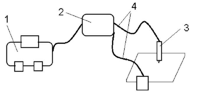
Figure 1 – The general device of the plasma cutter
2.1 Brief description of the plasma cutting process
To excite the working arc (the electrode is the metal being cut), an auxiliary arc is ignited between the electrode using an oscillator and the nozzle is the so-called duty arc, which is blown out of the nozzle by the starting air in the form of a torch 20-40 mm long figure 2.
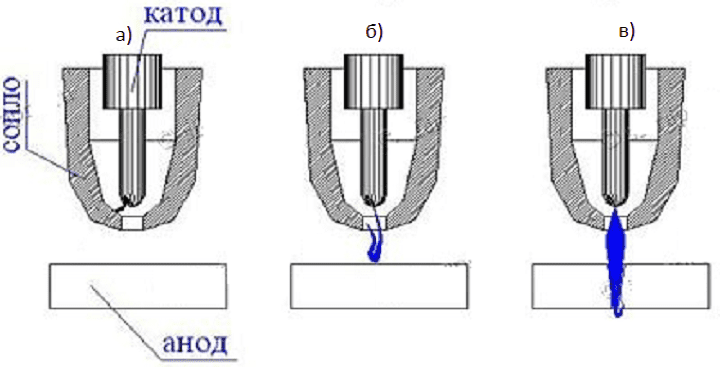
Figure 2 – Phases of working arc formation:
a) the origin of the duty arc;
b) blowing the duty arc until it touches the surface of the metal being cut;
c) the appearance of a working (cutting) arc and penetration through the metal cut
The current of the standby arc is 25 or 40 ... 60 A, depending on the source of the plasma arc. When touching the torch of the duty arc of metal , there is the cutting arc is working, and the increased air flow is turned on; the duty arc is automatically switched off.
The advantages of air-plasma cutting in comparison with mechanized oxygen and plasma cutting in inert gases are as follows:
- Simplicity of the cutting process;
- The use of inexpensive plasma-forming gas - air;
- High cut purity (when processing carbon and low-alloy steels);
- Reduced degree of deformation;
- A more stable process than cutting in hydrogen-containing mixtures.
2.2 The general structure and principle of operation of the plasma cutter
The main element of the machine is a plasma cutter or plasma torch, which consists of a nozzle, an electrode, a cooler (insulator) between them and a channel for supplying compressed air Figure 3.
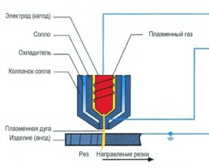
Figure 3 – Schematic diagram of the plasma cutter.
Inside the body of the plasma torch there is an electrode that serves to excite an electric arc. The nozzle of the plasma torch compresses and forms a plasma jet, which escapes from the output channel and cuts the workpiece. The compressor provides air supply. Plasma cutting technology involves the use of gases: plasma-forming and protective.
A cable-hose package connects the power supply, compressor and plasma torch. The current from the transformer is supplied via an electric cable or an inverter to excite an electric arc, and compressed air goes through the hose, which is necessary for the formation of plasma inside the plasma torch.
The principle of operation of the plasma cutter is as follows. When the power source (inverter) 2 is turned on, a high-frequency current enters the plasma torch. As a result , a standby electric arc occurs inside the plasma torch, the temperature of which is 6000 – 8000 ° C. The duty arc is ignited between the electrode and the nozzle tip, since the formation of an arc between the electrode and the workpiece is immediately difficult. The duty arc column fills the entire nozzle channel.
After the occurrence of the duty arc, compressed air begins to flow into the nozzle chamber. The nozzle of the plasma torch, narrowed to the bottom, compresses the air jet and forms a stream that escapes from the nozzle at a speed of 2-3 m/s. The air temperature at this moment can reach 25,000 – 30,000 °C. It is this high-temperature ionized air that is the plasma in this case.
Its electrical conductivity is approximately equal to the electrical conductivity of the metal being processed. At the moment when the plasma escapes from the nozzle and comes into contact with the surface of the processed metal, the cutting arc is lit, and the duty arc goes out. The cutting (working) arc heats up the workpiece locally at the cutting point. The metal melts, a cut appears.[8]
2.3 Overview of plasma cutting devices
Plasma cutting devices can be divided into two groups: manual plasma cutters and machine cutting machines (machines). Manual plasma cutters are used in everyday life, in small industries and in private workshops for the manufacture and processing of parts. With this method, the cut is smooth, but not ideal; the productivity of the operations performed is not high.
At machine-building enterprises, plasma cutting machines (machines) are used for the manufacture of parts or processing of workpieces, modern designs of which have CNC (numerical control). The CNC machine works according to a given program with minimal operator participation, which eliminates the human factor in production as much as possible and significantly increases productivity.
The cutting quality of the machine is perfect, no additional edge processing is required. Curly cuts are also provided. The duration of turning on the machine can reach 100%. The price of a plasma cutting machine, depending on the complexity and size, is 3000 ... 20,000 cu. It is possible to distinguish heavy, medium and small class machines. Portable machines also belong to small-class machines.
3. Description of the design of the model of a portable cnc plasma cutting machine
The main objective of the project is a detailed study of the design of a small-sized portable CNC plasma cutting machine. For this purpose, a three-dimensional model of the plasma cutter was created in the COMPASS computer-aided design system Figure 4. The scale of the computer model corresponded to natural dimensions.
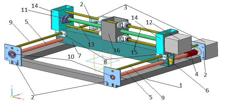
Figure 4 is a three–dimensional model of the developed portable plasma cutter.
The base of the machine 1 is a welded frame made of a profile pipe of square cross-section. On the frame mechanisms for moving the cutter along the X and Y axes are placed. On the side surfaces of the frame, support plates 2 are fixed on four sides, to two of which stepper motors 3 of the Y-axis movement mechanism are attached. The shafts of the engines are connected by means of flexible couplings 4 to screws 5, which together with nuts 6 form screw gears of the mechanism of movement along the Y axis. Nuts 6 are mounted inside the traverse 7, made of a rectangular profile pipe. Linear bearings 8 for guides 9 are fixed on the traverse. Two bearings for each guide. Guides 9 are cylindrical rods resting on plates 2. In addition, bearing housings 10 are fixed on plates 2 rolling bearings 11, which are the supports of the screws 5. Screw gears 5-6 convert the rotation of the shafts of the motors 3 into the translational movement of the traverse
A mechanism for moving the cutter along the X-axis is mounted on the traverse 7. The mechanism includes a stepper motor 12, which is connected to the screw 13 through a flexible coupling. The screw is supported by rolling bearings 11, the housings 10 of which are fixed on racks 14 mounted on the edges of the traverse 7. The racks 14 also act as guide supports 15. Along the guides 15 and the screw 13, the carriage 16 moves with a plasma torch 17 fixed on it. The nut that ensures the carriage movement is located inside the carriage 16. The housings 17 of the linear bearings 18 of the guides 17 are fixed to the carriage 17 from the outside.
4. Program setting of the plasma cutter
In order to cut a part on a CNC plasma cutter, you must first write a control program for the machine controller. The sequence of actions performed is shown below. 1. Creating a part drawing. To do this, open the program "COMPASS-3D" and create an image of the part Figure 2 in a file like fragment Figure 1.
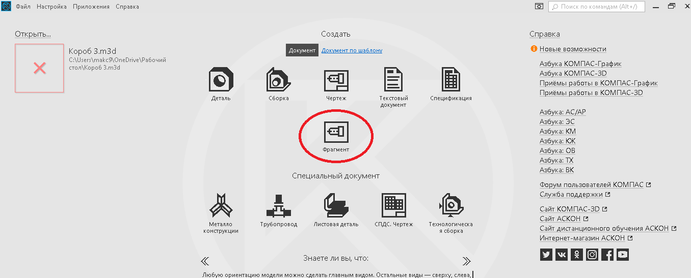
Figure 1 – Selection of a fragment type file in the COMPASS system
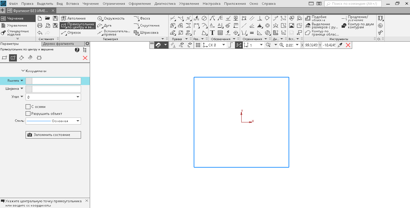
Figure 2 – Saving the part image
2.Save the part image in PNG format at a scale of 1:1 Figure 3.
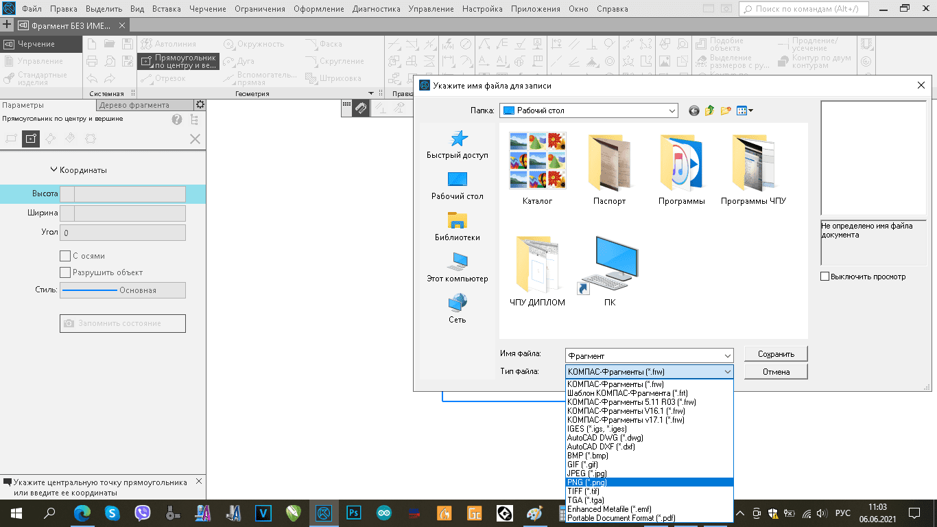
Figure 3 – Drawing an image of a part
3. Setting cutting settings for a part file. 3.1. Run the LaserGRBL program Figure 4 and select the saved file figure 5.
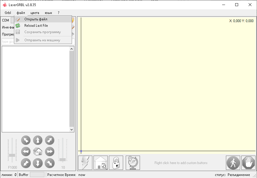
Figure 4 – LaserGRBL program interface
Figure 5 – File selection in the LaserGRBL program
3.2.In the window that opens, set the settings for cutting parameters.
1. Select the "Vectorize" parameter Figure 6. Click the "Yes" button.
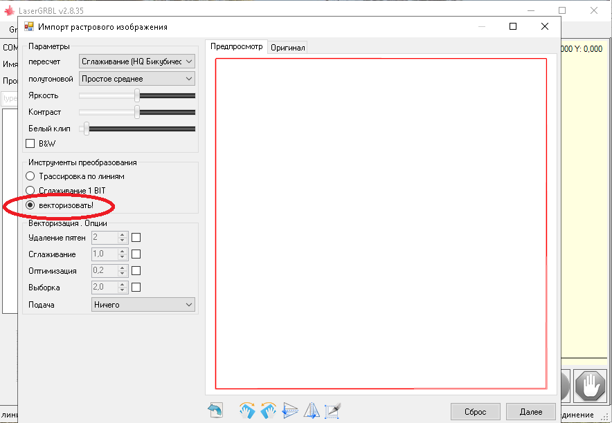
Figure 6 – Setting up vectorization
2. In the window that opens, set the overall dimensions of the part – width W and height H (mm) figure 7.
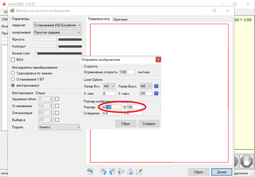
Figure 7 – Installation of the overall dimensions of the part
3. Set the minimum and maximum power values of the working body Figure 8.
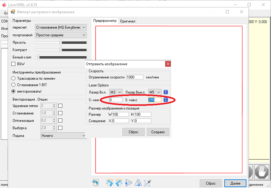
Figure 8 – Setting the power
4. Set the cutting speed limit (mm/min.) Figure 9.
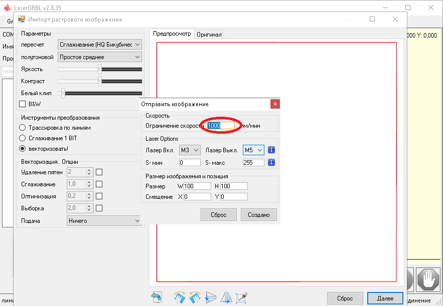
Figure 9 – Tincture of the cutting speed limit
5. Click the "Created" button.
3.3. Connecting the machine controller port to the program: 1. In the "COM port" field, select the COM3 port Figure 10 and click the "Connect" button.
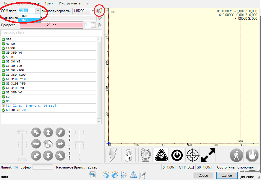
Figure 10 – Connection port selection
In the "Estimated Time" field, the approximate time for completing the task will be indicated, taking into account the specified settings Figure 11.

Figure 11 – Estimation of the required operating time of the machine
2. Move the axes. The arrow keys are responsible for the rotation of the axes of the machine, the slider on the left adjusts the speed of movement of all axes in mm/min., the slider on the right adjusts the distance of movement of the axes in mm, the central button returns the cutter to the "zero point" figure 12.
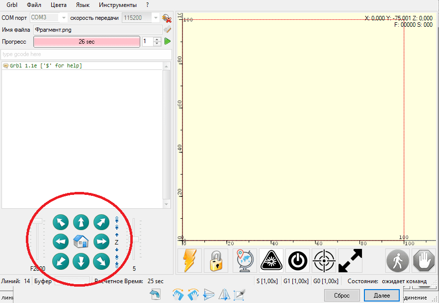
Figure 12 – Buttons for controlling the movement of the axes of the machine
3. To set the "Zero point", move the axes of the machine to the desired position on the workpiece and click on the "Globe" button figure 13, now the program will understand from which point it should start moving, and the cutter cursor on the working field of the program will shift to the rightmost position at the mark 0 figure 14.
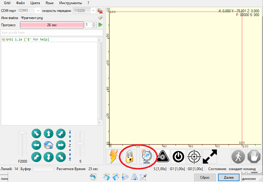
Figure 13 – Setting the cutter to the starting point ("zero point")
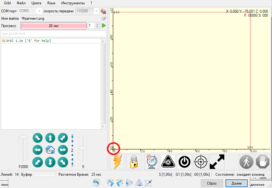
Figure 14 – The result of setting to the zero point
4. Launch of the program and the machine for the execution of the task. To do this, press the green "PLAY" button figure 15.
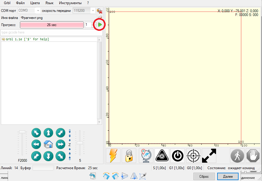
Figure 15 – Launching the program for execution
After pressing, the cutter cursor will start moving along the part line, and the Progress scale shows the amount of time worked by the program Figure 16.
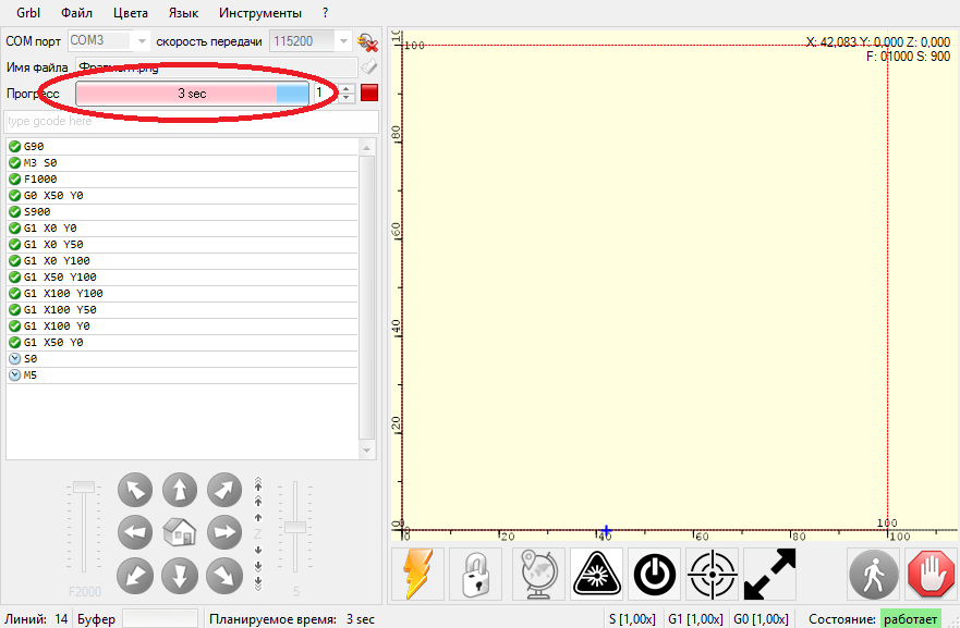
Figure 16 – Display of time worked
At the end of the work, the cutter will return to the zero point.
Conclusions
In the final qualifying work of the bachelor, a project of a full-scale model of a portable CNC plasma cutter was carried out. The analysis of information about portable machines is presented; brief information about plasma cutting technology, the types of plasma cutting machines are considered, their characteristics are given. The design of a portable plasma cutter is proposed, a three-dimensional model of the machine is created in the COMPASS computer-aided design system. Calculations were performed to determine the energy-power parameters of the cutter movement mechanisms along the X-axis and Y-axis, stepper motors, couplings, rolling bearings and linear guide bearings were selected. Verification strength calculations of screw gears were carried out. Recommendations on lubrication of friction units are given and a linear schedule of machine assembly is developed. Cost estimates have been compiled. The issues of occupational safety of personnel working at the plasma cutter are considered.
List of sources
- Yeremenko Yu.I. et al. Expert system of maintenance of tires. – Stary Oskol: SOF MISIS, 1999. – 306 p.
- Website https://ingeneryi.info. li>Anuryev A.A. Designer's Handbook. Vol.1. – M.: Mechanical Engineering, 2000. – 586 p.
- Ivanov A.S. We design machines. Step by step. In 2 parts. – Part 1. – Moscow: Publishing House of Bauman Moscow State Technical University, 2000. - 328 p.
- Ivanov A.S. We design machines. Step by step. In 2 parts. – Part 2. – Moscow: Publishing House of Bauman Moscow State Technical University, 2003. - 392 p.
- Perel L.Ya. Rolling bearings: Calculation, design and maintenance of supports: Handbook. - M.: Mechanical Engineering, 1983. – 543 p.
- Belkov, V.N. Fundamentals of calculation and design of screw mechanisms: textbook. manual / V. N. Belkov. – Omsk: Publishing house of OmSTU, 2008. – 160 p
- Sedush V.Ya. Reliability, repair and installation of metallurgical machines: Textbook. - K.: UMK VO, 1992. - 368 p.
- Gedyk P.K., Kalashnikova M.I. Lubrication of metallurgical equipment. –M.: Metallurgy, 1971. - 376 p.
- Rybanov V.M. Welding and cutting of metals. – M.: Higher School, 1979. – 214 p.